
Size Separation Introduction
Size separation is a unit operation that involves the separation of particles of a particular size range from a mixture of different-sized particles. It is generally the step next to the size reduction. After size reduction particles prepared have wide size distribution. The narrow size distribution is necessary to confer equal physicochemical properties. It is necessary for pharmaceutical preparations like suspensions to avoid Ostwald ripening in tablets to form granules.
Official Standards For Powder Size
According to Indian pharmacopeia, the size of the powder is expressed by a mesh the aperture size of the sieve through which powder can pass.
I.P. categorizes powders as follows:
- Coarse powders: A powder of which all the particles pass through a sieve with a nominal mesh aperture of 1.70 mm (No. 10 sieve) and not more than 40% through a sieve with a nominal mesh aperture of 355 pm (No. 44 sieve) is called coarse powder.
- Moderately coarse powder: A powder of which all the particles pass through a sieve with a nominal mesh aperture of 710 pm (No. 22 sieve) and not more than 40% through a sieve with a nominal mesh aperture of 250 pm (No. 60 sieve) is called moderately coarse powder.
- Moderately fine powder: If all particles of powder pass through a sieve with a nominal aperture of 355 pm (No. 44 sieve) and not more than 40% through a sieve with a nominal mesh aperture of 180 pm (No. 85 sieve) is called the moderately fine powder.
- Fine powder: If all the particles pass through a sieve with a nominal mesh aperture of 180 pm (No. 85 sieve) it is called a fine powder.
- Very fine powder: If all the particles pass through a sieve with a nominal mesh aperture of 125 pm (No. 120 sieve), it is called a very fine powder. In the United States Pharmacopoeia, powders are classified according to size as very coarse, coarse, moderately fine, fine, and very fine.
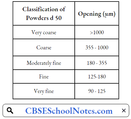
d50 is the smallest sieve opening through which 50% or more of the material passes
Objectives Of Size Reduction
- To obtain powders of desired size distribution. Any solid material after size reduction gives particles of different sizes. So to get the particles of the desired size range one must go through the size separation.
- During tablet granulation the granules should be within a narrow size range, otherwise, weight variation will take place during tablet punching.
- To obtain a stable suspension. If the dispersed phase contains particles of a wide size range then they may increase the Ostwald ripening.
- To avoid the variations in physicochemical properties.
- To set a quality control parameter for raw material.
- To improve mixing.
Applications Of Size Reduction Size Separation In Pharmaceutical Engineering
- Capsule filling: Uniform size particles are easy to fill in the capsules giving good flow properties.
- Tablet formulation: Uniform particle size ensures good flow from the hopper which avoids weight variation.
- It can serve as a quality control tool for the evaluation of raw materials.
- Removal of impurities based on size.
- Separation of solids from a gas suspension.
- Separation of coarse particles after levigation.
- Drugs that are intended for oral use should have a very small size (10 pm). So, much smaller-sized particles are separated by centrifugal classifiers.
- In the extraction process, the optimum size is needed to use for efficient extraction. For example, for extraction from Ashoka bark coarse powder is specified whereas for extraction from Rauwolfia root a moderately coarse powder is indicated.
Size Separation Sieves Size Separation In Pharmaceutical Engineering
A sieve is a surface having several apertures of specific dimensions.
- A material to be sieved is passed on the surface of the screen and agitated.
- The particles having a size less than the aperture size of the sieve are passed through the sieve where whereas the particles having a size more than the aperture are retained on the surface of the sieve.
- So, the particles of material get separated based on their size after sieving. By using sieves of different sizes the powder can be separated and graded.
- Sieves for pharmacopoeial testing are constructed from wire cloth with square meshes, woven from wires of brass, bronze, stainless steel, or any other suitable metal
- The wires should be of uniform circular cross-section and should not be coated or plated. Sieve metals should be compatible with the drugs to be screened.
Standards for Sieves
Sieves used for pharmacopoeial testing must specify the following:
- Number of sieves: The sieve number indicates the number of meshes in a length of 2.54 cm in each transverse direction parallel to the wires.
- Nominal size of aperture: Nominal size of aperture indicates the distance between the wires. It represents the length of the side of the square aperture. The I.P. has given the nominal mesh aperture size for the majority of sieves in mm or in μm.
- Nominal diameter of the wire: Wire mesh sieves are made from the wire having the specified diameter to give suitable aperture size and sufficient strength to avoid distortion of the sieve.
- Approximate percentage sieving area: This standard expresses the area of the meshes as a percentage of the total area of the sieve. It depends on the size of the wire used for any particular sieve number. Generally, the sieving area is kept within the range of 35 to 40 percent to give suitable strength to the sieve.
- Tolerance average aperture size: Some variation in the aperture size is unavoidable and when this variation is expressed as a percentage, it is known as the ‘aperture tolerance average’.
- It is a limit given by pharmacopeia within which a particular dimension or average aperture size can be allowed to vary and still be acceptable for the purpose for which it is used.
- Fine meshes cannot be woven with the same accuracy as coarse meshes.
- Hence the aperture tolerance average is smaller for coarse sieves than the fine sieves.
Size Separation Mechanisms
Mechanical sieving devices are usually based on methods that agitate or brush the sieve or use centrifugal force.
- Agitation: Sieves may be agitated in several different ways, for example:
- Oscillation: The sieve is mounted in a frame that oscillates back and forth. The method is simple. The material may roll on the surface of the sieve, fibrous materials can form a ball of material.
- Vibration: In this method, the sieve is vibrated at high speed electrically. The high speed of vibration is applied to the particles on the sieve. So the particles do not block the mesh.
- Gyration: The gyratory method uses a system in which the sieve is on a rubber mounting and connected to an eccentric flywheel.
- Thus, the sieve is given a rotary movement of small amplitude, but of considerable intensity, giving a spinning motion to the particles.
- This increases the chances of a particle becoming suitably oriented to pass through the mesh so that the output is usually considered greater than that obtained with oscillating or vibratory sieves.
- Agitation methods may be made continuous, by the inclination of the sieve and the provision of separate outlets for undersized and oversized particles.
- This applies irrespective of the method of agitation.
- Brushing: A brush can be used to move the particles on the surface of the sieve and to keep the meshes clear. A single brush across the diameter of an ordinary circular sieve, rotating about the mid-point is effective, but in large-scale production, a horizontal cylindrical sieve is employed, with a spiral brush rotating on the longitudinal axis of the sieve.
- Centrifugal: A mechanical sieve of this type normally uses a vertical cylindrical sieve with a high-speed rotor inside the cylinder, so that particles are thrown outwards by centrifugal force. The current of air created by the movement assists sieving also, and is especially useful with very fine powders
Size Separation Instruments Size Separation In Pharmaceutical Engineering
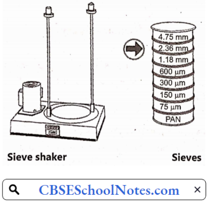
1. Sieve Shaker
Sieve Shaker Principle:
The materials are separated based on their size due to high-speed vibratory motion. The finest particles are collected at the bottom sieve or the collecting pan and the particles having the largest size are collected in the upper sieve.
Sieve Shaker Construction:
In the sieve shaker, a set of sieves is used. These sieves are arranged in descending order i.e. sieve of a larger size is at the top and the sieve having the smallest size is placed at the bottom. The bottom sieve is attached to the receiving pan. The size separation is done by passing the powder through these sieves.
Sieve Shaker Working:
The powder is placed in the upper sieve. The sieves are shaken with the help of mechanical sieve shakers or electromagnetic devices. This motion helps the particles to pass through the sieve. After a particular period of shaking some weight of the powder is retained on each sieve depending on its size
Sieve Shaker Use:
It can be used for handling a variety of dry powders, granules, and dry foods.
Sieve Shaker Advantages:
- It requires less area for operation.
- It is a fast and more accurate process.
- High speed of vibration avoids the blockage of the sieve.
Sieve Shaker Disadvantage:
Sieves should be used and stored with care, since if the sieve becomes damaged or distorted then it is of little value.
2. Cyclone Separator
Very low rates of separation are achieved if separation is done under the influence of gravitational force, especially at low velocities and low particle size. So, the separation can be enhanced by using centrifugal force. The cyclone separator works based on centrifugal force.
Cyclone Separator Principle:
In a cyclone separator, centrifugal force is used to separate solids from fluids. The separation process depends on particle size and particle density. It is also possible to allow fine- particles to be carried with the fluid.
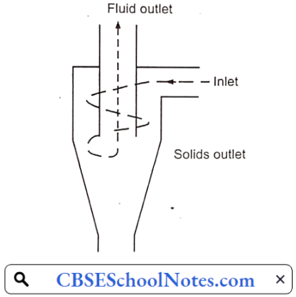
Cyclone Separator Construction:
It consists of a short vertical, cylindrical vessel with a conical base. The upper part of the vessel is fitted with a tangential inlet The solid outlet is at the base. A fluid outlet is provided at the center of the top portion, which extends inwardly into the separator. Such an arrangement prevents the air from short-circuiting directly from the inlet to the outlet of the fluids.
Cyclone Separator Working:
The solids to be separated are suspended in a stream of fluid (usually air or water). Such feed is introduced tangentially at a very high velocity so that rotary movement takes place within the vessel. The centrifugal force throws the particles to the wall of the vessel. As the speed of the fluid (air) diminishes, the particles fall to the base and are collected at the solid outlet. The fluid (air) can escape from the central outlet at the top.
Cyclone Separator Advantages:
- Low capital cost.
- Relative simplicity and few maintenance problems.
- Low-pressure drop (ca. 2-6 w.c.).
- Dry collection and disposal.
- Relatively small space requirements.
- No moving parts.
- Can be used under extreme processing conditions.
Cyclone Separator Disadvantages:
- Offer low particulate collection efficiencies, especially for particulate sizes below 5 pm.
- Inability to handle sticky materials.
Cyclone Separator Uses:
- Cyclone separators are used to separate solid particles from gases.
- It is also used for size separation of solids in liquids.
- It is used to separate the heavy and coarse fractions from fine dust.
- It is used in oil refineries to separate oils and gases.
3. Air Separator
Air Separator Principle:
The cyclone separator alone cannot- carry out size separation on fine materials. For such separations, a current of air combined with centrifugal force is used. The finer particles are carried away by air and the coarse particles are thrown by centrifugal force, which fall at the bottom.
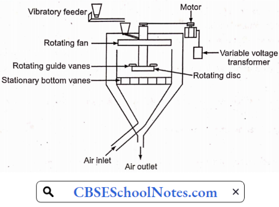
Air Separator Construction:
It consists of a cylindrical vessel with a conical base. A rotating plate is fitted on a shaft placed at the center of the vessel. A set of fan blades are also fitted with the same shaft.
At the base of the vessel, two outlets are provided:
- One for the finer particles and
- The other is for coarse particles.
Air Separator Working:
The disc and the fan are rotated using a motor. The feed (powder) enters at the center of the vessel and falls on the rotating plate. The rotating fan blades produce a draft (flow) of air in the direction. The fine particles are picked up by the draft of air and carried into the space of the settling chamber, where the air velocity is sufficiently reduced so that the fine particles are dropped and removed through the fine particle outlet. Particles too heavy to be picked up by the air stream are removed at the coarse particle outlet
Air Separator Uses:
Air separators are often attached to the ball mill or hammer mill to separate and return oversized particles for further size reduction
Air Separator Advantages
- It gives efficient separation in smaller apparatus.
- The waste does not interact with the generator of the airflow, avoiding wear and clogging.
- Low maintenance.
- High reliability.
- Low-pressure drop.
Air Separator Disadvantages
- Low separation yield.
- Unsuitable for separating smaller particles.
4. Filter Bag
Filter Bag Principle:
In filter bags, the separation of fine powder from coarse powder is carried out by applying suction. Firstly the mixture of powder which is to be separated is passed through a bag which is made up of cloth by applying suction at opposite side of the feeding. This causes the separation of fine and coarse powder. After this separation, the bags are shaken by giving pressure to remove the powder that is adhered to the bags. After that powder is collected from a conical base.
Filter Bag Construction:
It consists of several bags made of cotton or wool fabric. These are suspended in a metal container. A hopper is arranged at the bottom of the filter to receive the feed. At the top of the metal container, a provision is made for a vacuum fan and exhaust through the discharge manifold. At the top of the vessel, a bell-crank lever arrangement is made to change the action from filtering to shaking
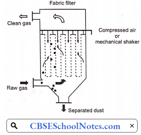
Filter Bag Working:
- Filtering period: During this period the vacuum fan produces a pressure lower than the atmospheric pressure within the vessel. Gas to be filtered enters the hopper, passes through the bags, and out of the top of the apparatus. The particles are retained within the bags.
- Shaking period: During this period the bell-crank lever first closes the discharge manifold and air enters through the top so the vacuum is broken. At the same time, it gives a violent jerking action to the bags so that they are freed from the dust. The fine particles are collected at the conical base.
Filter Bag Uses:
- Bag filters are used along with other size separation equipment, e.g. a cyclone separator.
- They are used on the top of a fluidized bed dryer for drying to separate the dust.
- They are used to clean the air of a room.
- The household vacuum cleaner is a simple version of a bag filter.
Filter Bag Advantages:
- A bag filter is extremely useful for removing fines, which cannot be separated by other methods.
- These can be used to remove dust.
- Reduced sensitivity to particle size distribution.
- No high voltage requirements
Filter Bag Disadvantages:
- It has a high resistance which is about 600-1200 P.
- Fabric life may be substantially shortened in the presence of high-acid or alkaline atmospheres, especially at elevated temperatures.
- Collection of hygroscopic materials or condensation of moisture can lead to fabric plugging, loss of cleaning efficiency, and large pressure losses.
5. Elutriation Tank
Elutriation is a method of separation of particles based on their density. The smaller size particles have low density whereas the particles of larger size have more density. These particles are separated using a fluid flow.
Elutriation Tank Principle:
The separation in the elutriation tank is based on the density of the particles which depends on the size of the particles. After levigation, the material is kept in an elutriating tank and mixed with a large quantity of water. Then depending on the density of the particle it will either settle down or it will be suspended in water. Then the sample is collected at different heights.

Elutriation Tank Construction:
The apparatus consists of a vertical column with an inlet near the bottom of the suspension, an outlet at the base for coarse particles, and an overflow near the top of fluid and fine particles. One column will give a single separation into two fractions. If more than one step separation is required multiple tubes can be used in a serial connection.
Elutriation Tank Working:
The material which is to be separated is first legated. Then this paste or powder is kept in an elutriating tank and a large quantity of water is poured into the tank. The content of the tank is mixed with the water by stirring. The particles are uniformly distributed in the water. They are allowed to settle for some time.
The particles which are having large sizes (high density) will settle down and the particles with smaller sizes will remain suspended in the liquid. If the tank contains outlets at different heights then the multiple fractions can be separated by containing the particles of different size ranges. Then these fractions are dried to collect the powder.
Elutriation Tank Uses:
This technique is useful for separation of insoluble solids. These solids are first subjected to grinding and then elutriation.
Elutriation Tank Advantages:
- It is a continuous process.
- Several fractions can be collected by using columns of different areas.
- The separation is quick as compared to sedimentation.
Elutriation Tank Disadvantage:
Dilution of suspension may be undesirable in some cases
Size Separation Size Separation In Pharmaceutical Engineering Multiple Choice Questions
Question 1. Which one of the following indicates a nominal size of aperture?
- Area of mesh as a percentage
- Distance between two adjacent wires
- Number of meshes per linear length
- A wire having a specified diameter that gives a suitable aperture
Answer: 3. Number of meshes per linear length
Question 2. Size classification is also known as
- Size separation
- Size reduction
- Size distribution
- Size analysis
Answer: 1. Size Separation
Question 3. The brushing method enhances the movement of
- Coarse materials
- Light materials
- Sticky materials
- Crystalline materials
Answer: 3. Sticky materials
Question 4. In cyclone separator, the separation depends on
- Density and shape
- Shape and surface area
- Size and density
- Surface texture and size
Answer: 3. Size and density
Question 5. In the air separator centrifugal force for the circulation of air is supplied by
- Applying vacuum
- Atomizing air
- Pumping
- Rotating blades
Answer: 4. Rotating blades
Question 6. Which mechanism helps in size separation by the sieve shaker?
- Centrifugal force
- Sedimentation
- Brushing
- Shearing forces
Answer: 4. Shearing forces
Question 7. A screen that sharply separates the feed mixture is called as
- Actual screen
- Ideal screen
- Virtual screen
- Real screen
Answer: 4. Real screen
Question 8. The disadvantage of a sieve shaker is
- Attrition
- Capacity limited
- Expensive equipment
- Tedious
Answer: 2. Capacity limited
Question 9. The movement of particles can be enhanced during size separation by one of the following modes.
- Agitation
- Attrition
- Gravitation
- Mixing
Answer: 1. Agitation