Class 12 Physics Chapter 7 Alternating Current Multiple Choice Questions And Answers
Question 1. A capacitor and an inductor are connected in two different AC circuits with a bulb glowing in each circuit. The bulb glows more brightly when:
- The number of turns in the inductor is increased
- The separation between the plates of the capacitor is increased
- An iron rod is introduced into the inductor
- A dielectric is introduced into the gap between the plates of the capacitor
Answer: 4. A dielectric is introduced into the gap between the plates of the capacitor
Read and Learn More Important Questions for Class 12 Physics with Answers
Question 2. A pure inductor of 318mH and a pure resistor of 75 Ω arc connected in series to an AC source of 50 Hz. The voltage across the 75 Ω resistor is found to be 150V. The source voltage is:
- 150 V
- 175 V
- 220 V
- 250 V
Answer: 4. 250 V
⇒ \(\cos \phi=\frac{R}{Z}=\frac{V_R}{V} \text { or } V=V_R \times \frac{Z}{R}\)
∴ \(\frac{150}{75} \sqrt{75^2+\left(3.14 \times 318 \times 10^{-3}\right)^2}=2 \sqrt{5625 \times 9970}=2 \times 124.8 \simeq 2.50 \mathrm{~V}\)
Question 3. In an AC circuit, the applied voltage and resultant current are E = E0 sin ωt and I = I0 sin (ωt + π/2) respectively. The average power consumed in the circuit is:
- B0I0
- \(\frac{E_0 I_0}{2}\)
- \(\frac{E_0 I_0}{\sqrt{2}}\)
- Zero
Answer: 4. Zero
∴ \(P_{avg}=E_{rms} I_{rms} \cos 90^{\circ}=0\)
Question 4. In a series LCR circuit, at resonance, the current is equal to_____
- \(\frac{\mathrm{V}}{\mathrm{R}}\)
- \(\frac{\mathrm{V}}{\mathrm{x}_{\mathrm{c}}}\)
- \(\frac{V}{X_{L}-X_C}\)
- \(\frac{V}{\sqrt{R^2+\left(X_L+X_C\right)^2}}\)
Answer: 1. \(\frac{\mathrm{V}}{\mathrm{R}}\)
Question 5. The frequency of an AC source for which a 10 μF capacitor has a reactance of 1000 ohm is___
- \(\frac{1000}{\pi} \mathrm{Hz}\)
- 50 Hz
- \(\frac{50}{\pi} \mathrm{Hz}\)
- \(\frac{100}{\pi} \mathrm{Hz}\)
Answer: 3. \(\frac{50}{\pi} \mathrm{Hz}\)
⇒ \(X_C=\frac{1}{2 \pi \mathrm{fC}}=1000\)
∴ \(f=\frac{50}{\pi} \mathrm{Hz} \)
Question 6. Which one of the following statements is true:
- An inductor has infinite resistance in a DC circuit.
- An inductor and a capacitor cannot conduct in a DC circuit
- A capacitor can conduct in a DC circuit but not an inductor.
- An inductor can conduct in a DC circuit but not a capacitor.
Answer: 4. An inductor can conduct in a DC circuit but not a capacitor.
Question 7. In an A.C. circuit in 1 second current reduces to zero value 120 times. Hence the frequency of A.c current is ___________ Hz.
- 50
- 100
- 60
- 120
Answer: 3. 60
Question 8. What is the r.m.s. value of the current for A.C. current I = 100 cos (200 t + 45°)A.
- 50√2 A
- 100 A
- 100√2 A
- Zero
Answer: 1. 50√2 A
∴ \(I_{\mathrm{rms}}=\frac{I_0}{\sqrt{2}}=\frac{100}{\sqrt{2}} \times \frac{\sqrt{2}}{\sqrt{2}}=50 \sqrt{2} \mathrm{~A}\)
Question 9. In an R-C circuit when the charge on the plates of the capacitor is increasing, the energy obtained from the sources is stored in ___________.
- Electric field
- Magnetic field
- Gravitational field
- Both Magnetic field and gravitational field
Answer: 1. Electric field
Question 10. The output power in a step-up transformer is ___________
- Greater than the input power
- Equal to the input power
- Maintained even during the power cut
- Less than the input power
Answer: 4. Less than the input power
Question 11. The power factor for scries L-R A.C. circuit is ________.
- \(\frac{\mathrm{R}}{\mathrm{X}_{L}}\)
- \(\frac{X_L}{R}\)
- \(\frac{R}{\sqrt{R^2+X_L^2}}\)
- \(\frac{\sqrt{R^2+X_L^2}}{R}\)
Answer: 3. \(\frac{R}{\sqrt{R^2+X_L^2}}\)
Question 12. An alternating voltage given as V = 200 √2 sin 100 l (V) is applied to a capacitor of 5μF. The current reading of the ammeter will be equal to _________mA.
- 80
- 20
- 40
- 100
Answer: 4. 100
⇒ \(I_{\mathrm{rms}}=\frac{V_{\mathrm{rms}}}{X_c}=\frac{V_0 / \sqrt{2}}{1 /\mathrm {\omega}{c}}=20\mathrm{\omega}{c}\)
∴ 200 z 100 x 5 x 10-6 = 10-1 A = 100 x 10-3 A = 100 mA
Question 13. The current of \(\frac{50}{\pi}\) frequency is passing through an A.C. circuit having a series combination of resistance R = 100 Ω and inductor L = 1H, then phase difference between voltage and current is __________.
- 60°
- 45°
- 30°
- 90°
Answer: 2. 45°
⇒ \(\phi=\tan ^{-1}\left(\frac{x_1}{R}\right)=\tan ^{-1}\left(\frac{2 \pi f L}{R}\right)\)
∴ \(\phi=\tan ^{-1}\left(\frac{2 \times \pi \times\frac{50}{\pi} \times 1}{100}\right)=45^{\circ}\)
Question 14. A coil of inductance L and resistance R is connected to an A.C. source of V volt. If the angular frequency of the A.C. source is equal to co rad s-1, then the current in the circuit will be __________.
- \(\frac{\mathrm{V}}{\mathrm{R}}\)
- \(\frac{\mathrm{V}}{\mathrm{L}}\)
- \(\frac{V}{R+L}\)
- \(\frac{V}{\sqrt{R^2+\omega^2 L^2}}\)
Answer: 4. \(\frac{V}{\sqrt{R^2+\omega^2 L^2}}\)
Question 15. In an A.C. circuit current is 2A and voltage is 220 V and power is 44 W power factor is _________.
- 0.10
- 0.09
- 1.80
- 0.18
Answer: 1. 0.10
Pvirtual = VI = 220 x 2 = 440 Watt
Pavg = Pvirtual cos Φ
44 = 440 x cos Φ
∴ \(\cos \phi=\frac{1}{10}=0.1\)
Question 16. A 15 μF capacitor is connected to a 220, 50 Hz a.c. source. The value of capacitive reactance is ___________.
- 424
- 106
- 212
- 21.2
Answer: 3. 212
⇒ \(X_C=\frac{1}{2 \pi f C}=\frac{1}{2 \times 3.14 \times 50 \times 1.5 \times 10^{-6}}\)
∴ Xc = 212.314
Question 17. A power transmission line feeds input power at 3300 V to a step-down transformer with its primary windings having 2000 turns. What should be the number of turns in the secondary to gel output power at 330 V?
- 200
- 400
- 33
- 40
Answer: 1. 200
⇒ \(\frac{V_s}{V_p}=\frac{N_s}{N_p}\)
⇒ \(\frac{330}{3300}=\frac{N_s}{2000}\)
⇒ \(\frac{1}{10}=\frac{N_s}{2000}\)
∴ Ns = 200
Class 12 Physics Chapter 7 Alternating Current Assertion and Reason
For question numbers 1 to 7 two statements are given-one labelled Assertion (A) and the other labelled Reason (R). Select the correct answer to these questions from the codes (1). (2). (3) and (4) as given below.
- Both A and R are true and R is the correct explanation of A
- Both A and R are true but R is NOT the correct explanation of A
- A is true but R is false
- A is false and R is also false
Question 1. Assertion: In a Series LCR circuit connected to an AC source, resonance can take place.
Reason: At resonance XL = XC
Answer: 2. Both A and R are true but R is NOT the correct explanation of A
Question 2. Assertion: A transformer is used to increase or decrease AC voltage only.
Reason: A transformer works based on mutual Induction.
Answer: 1. Both A and R are true and R is the correct explanation of A
Question 3. Assertion: Average power loss in scries LC circuit is always zero.
Reason: The average value of voltage and current in A.C. is zero.
Answer: 2. Both A and R are true but R is NOT the correct explanation of A
Question 4. Assertion: The capacitor serves as a block for D.C, and offers an easy path to AC.
Reason: Capacitive reactance is inversely proportional to frequency.
Answer: 1. Both A and R are true and R is the correct explanation of A
Question 5. Assertion: When capacitive reactance is smaller than the inductive reactance in the scries LCR
circuit, voltage leads the current.
Reason: In a series LCR circuit inductive reactance is always greater than capacitive reactance.
Answer: 3. A is true but R is false
Question 6. Assertion: In the series LCR circuit, the impedance is minimal at resonance.
Reason: The currents in the inductor and capacitor arc same in the scries LCR circuit.
Answer: 2. Both A and R are true but R is NOT the correct explanation of A
Question 7. Assertion: In series LCR circuit phase difference between current and voltage is never zero.
Reason: Voltage and current are never in phase.
Answer: 4. A is false and R is also false
Class 12 Physics Chapter 7 Alternating Current Short Questions And Answers
Question 1. An alternating current I = (10 A) sin (100 πt) is passed through a resistor of 20 Ω. What is the average power consumed by the resistor over a complete cycle?
Answer:
Pavg= Vrms Irms cos = (Irms R) Irms [cosΦ= 1]
So, Pavg = I2rms R-C
⇒ \(\frac{I_{0}^2}{2} \times R\)
⇒ \(\frac{10 \times 10 \times 20}{2}\)
Pavg = 1000 watt
Question 2. Define ‘quality factor’ at resonance in series LCR circuit. What is its SI unit?
Answer:
The Q factor of the series resonant circuit is defined as the ratio of the voltage developed across the inductor or capacitor at resonance to the applied voltage, which is the voltage across R.
⇒ \(Q=\frac{I X_1}{I R}=\frac{{\omega}_0 L}{R}=\frac{{\omega}_1}{{\omega}_2-{\omega}_1}\)
It is dimensionless, hence it has no units. It represents the sharpness of resonance.
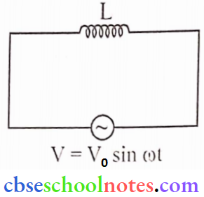
Question 3. An a.c. source of voltage V = V0sinωt is connected to an ideal inductor. Draw graphs of voltage V and current 1 versus cot.
Answer:
Question 4. Explain why current Hows through an ideal capacitor when it is connected to an a.c. source but not when it is connected to a D.C. source in a steady state.
Answer:
When AC is connected to the capacitor, due to continuous change of polarity of the applied voltage there will be continuous change of polarity of capacitor plates. This causes the charge to flow across the capcitor.
In steady state, the capacitor acts as an open circuit as reactance offered by it to flow of dc (f = 0) is infinite, As \(X_c=\frac{1}{2 \pi f C}=\infty\)
Question 5.
An LCR series circuit is connected to an AC source. If the angular resonant frequency of the circuit is coo, will the current lead or lag or be in phase with the voltage when to ω < ω0 and why?
- We cannot step up the DC voltage using a transformer. Why?
- On what principle does a metal detector work?
Answer:
1. at ω < ω0
XL< XC
so current leads the voltage
2. For d.c f = 0
So. there is no mutual induction and the transformer works on the principle of mutual induction.
3. The metal detector works on the principle of resonance in AC circuits.
Question 6.
- In an LCR series circuit connected to an AC source, the voltage and the current are in the same phase. If the capacitor is filled with a dielectric, will the current lead or lag or remain in phase with the voltage? Explain.
- In the circuit, why is the rms value of net voltage not equal to the sum of voltage drops
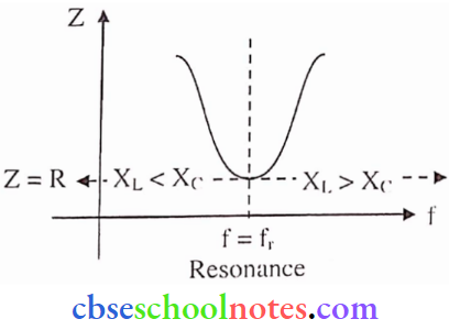
across individual elements? - Draw a graph showing variation of the impedance of the circuit with the frequency of the
applied voltage.
Answer:
1. Given in question capacitor is filled with a dielectric slab, So new capacity increases as
⇒ \(C=\frac{\varepsilon_1 \varepsilon_0 A}{d}\)
So, C increase then XC decreases
So, XL > XC
Current lag voltage, as the circuit is inductive.
2. Voltage across R, L, and C are at different phase angles. So. we must do vector addition of voltages then we get Net voltage.
3. 
Question 7. A capacitor of unknown capacitance, a resistor of 100 Ω, and an inductor of self-inductance l, = (4/π2) henry are connected in series to an AC source of 200 V and 50 Hz. Calculate the value of the capacitance and impedance of the circuit when the current is in phase with the voltage. Calculate the power dissipated in the circuit.
Answer:
Current in phase with voltage means the angle between cmf and current is zero. This is a resonance condition. So
Inductive reactance = Capacitive Reactance
⇒ \(X_L=X_C \Rightarrow \omega L=\frac{1}{\omega C}\)
⇒ \(\mathrm{C}=\frac{1}{{\omega}^2 \mathrm{~L}} \text {, given } \mathrm{L}=4 / \pi^2 \quad f=50 \mathrm{~Hz}, \mathrm{~V}=200 \mathrm{~V}\)
So \(C=\frac{1 \times \pi^2}{(2 \pi)^2 \times 4 \times(50)^2} \Rightarrow C=25 \mu \mathrm{F}\)
Power dissipated \(P=V^2 / R=\frac{200 \times 200}{100}\)
∴ P = 400 W
Question 8. A series LCR circuit connected to a variable frequency 230 V source.
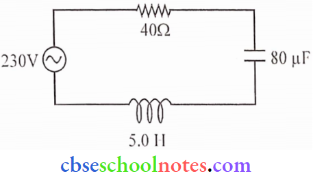
- Determine the source frequency which drives the circuit in resonance.
- Calculate the impedance of the circuit and amplitude of current at resonance.
- Show that potential drop across LC combination is zero at resonating frequency.
Answer:
1. At Resonance
⇒ \(X_L=X_C \Rightarrow \omega_{\mathrm{r}} L=\frac{1}{\omega_{\mathrm{r}} \mathrm{C}}\)
⇒ \(f_r=\frac{1}{2 \pi \sqrt{L C}} \Rightarrow f_r=\frac{1}{2 \pi \sqrt{5 \times 80 \times 10^{-6}}}\)
⇒ \(f_r=\frac{1}{2 \pi \times 20 \times 10^{-3}}\)
∴ \(\mathrm{f}_{\mathrm{r}}=\frac{25}{\pi} \mathrm{Hz}\)
2. Impedance of the circuit at resonance
Z = R = Z = 40 Ω
Amplitude of current at resonance
⇒ \(V_{\mathrm{rms}}=I_{\mathrm{rm}} \mathrm{Z} \Rightarrow I_{\mathrm{rms}}=\frac{230}{40} \mathrm{A}\)
∴ \(I_{\mathrm{rms}}=\frac{23}{4} \mathrm{~A}\)
Amplitude, I0 = √2 Irms
∴ I0 = 8.1 A
3. Potential drop across LC combination
VLC = VL-VC
= I(XL-XC)
At resonance XL = XC => XL– XC = 0
VC= 0
Question 9.
- When an AC source is connected to an ideal capacitor, show that the average power
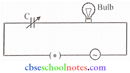
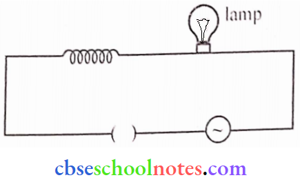
supplied by the source over a complete cycle is zero. - A bulb is connected in series with a variable capacitor and an A.C. source as shown. What happens to the brightness of the bulb when the key is plugged in and the capacitance of the capacitor is gradually reduced?
Answer:
1. Given V = V0 sin t
q = CV
q = CV0 sin t
⇒ \(\frac{\mathrm{dq}}{\mathrm{dt}}=\mathrm{CV}_0 \quad \frac{\mathrm{d}}{\mathrm{dt}} \sin \omega t\)
I = CV0 (cos ω t)
⇒ [\atex]\left.I=\frac{V_0}{\left(\begin{array}{c}\frac
{1}{\omega c}
\end{array}\right)} \cos {\omega} t \Rightarrow I=\frac{V_0}{X_c} \sin ({\omega} t+\pi / 2\right)[/latex]
Here, \(X_C=\frac{1}{{\omega} C} \text { and } \mathrm{I}_0=\frac{V_0}{X_C}\)
Average power
⇒ \(P_{a v}=\int_0^1 V I d t=\frac{V_0^2}{X_C} \int_0^1(\sin {\omega} t)(\sin {\omega} t+\pi / 2) d t=\frac{V_0^2}{X_c} \int_0^1(\sin \omega t)(\cos {\omega}t) d t\)
⇒ \(P_{\mathrm{av}}=\frac{\mathrm{V}_0^2}{2 X_C} \int_0^{\mathrm{T}} \sin (2{\omega} t) d t \quad\left\{\int_0^{\mathrm{T}} \sin (2{\omega} t) d t=0\right.\)
Pav = 0
2. When the AC source is connected, the capacitor offers capacitive reactance XC = 1/Cω. The
current flows in the circuit and the lamp glows. On reducing C, XC increases and currently
reduces, Therefore, the bulb’s glow reduces.
Question 10. A capacitor (C) and resistor (R) are connected in series with an AC source of voltage of frequency 50 Hz. The potential difference across C and R are 120 V and 90 V respectively, and the circuit’s current is 3 A. Calculate
- The impedance of the circuit
- The value of the inductance, which when connected in series with C and R will make the power factor of the circuit unity.
Answer:
Given: f = 50 Hz, I = 3A, VC = 120 V and VR = 90 V
1. Impedance of the circuit:
⇒ \(\mathrm{Z}=\frac{\mathrm{V}}{\mathrm{I}} \Rightarrow \mathrm{Z}=\frac{\sqrt{\mathrm{V}_{\mathrm{c}}^2+\mathrm{V}_{\mathrm{R}}^2}}{\mathrm{I}}\)
⇒ \(Z=\frac{\sqrt{(120)^2+(90)^2}}{3}\)
Z = 50
2. Power factor (cos Φ) = l. This is the condition of resonance. Let inductance (L) is connected in series with C and R. At resonance.
XL = XC
VC = IXC
120 = 3 XC
XC = 40
XL = 40 Ω ⇒ ωL = 40 Ω ⇒ 2πfL = 40
π \(\mathrm{L}=\frac{40}{2 \pi f}=\frac{40}{2 \pi \times 50}=\frac{0.4}{\pi} \mathrm{H}\)
Question 11.
- When an AC source is connected to an ideal inductor show that the average power supplied
by the source over a complete cycle is zero. - A lamp is connected in series with an inductor and an AC source. What happens to the lamp’s brightness when the key is plugged in and an iron rod is inserted inside the inductor? Explain.
Answer:
1. Given
V = V0 sinωt
⇒ \(\mathrm{V}=\mathrm{L} \frac{\mathrm{d} \mathrm{I}}{\mathrm{dt}}\) (induced emf)
⇒ \(\mathrm{dI}=\frac{\mathrm{V}}{\mathrm{L}} \mathrm{dt}\)
⇒ \(\mathrm{dI}=\frac{\mathrm{V}_0}{\mathrm{~L}} \sin \omega t \mathrm{dt}\)
By integration \(I=\frac{-V_0}{{\omega}} \cos {\omega} t\)
∴ \(I=-\frac{V_0}{\omega L} \sin \left[\frac{\pi}{2}-\omega t\right] \Rightarrow I_0 \sin \left[\omega t-\frac{\pi}{2}\right]\)
where \(I_0=\frac{V_0}{{\omega} \mathrm{L}}\)
Average power
⇒ \(P_{\mathrm{av}}=\int_0^{\mathrm{T}} V I \mathrm{dt}\)
⇒ \(-\frac{V_0^2}{\omega L} \int_0^T \sin {\omega} t \cos {\omega}t dt\)
⇒ \(-\frac{V_0^2}{2 \omega L} \int_0^{\mathrm{T}} \sin (2 \omega \mathrm{t}) \mathrm{dt} \quad\left\{\int_0^{\mathrm{T}} \sin (2 \omega t) \mathrm{d} t=0\right.\)
= 0
2. When an iron rod is inserted into the inductor, the self-inductance of the inductor increases. On increasing L. XL increases and current reduces. Therefore glow of the bulb reduces.
Class 12 Physics Chapter 7 Alternating Current Long Questions And Answers
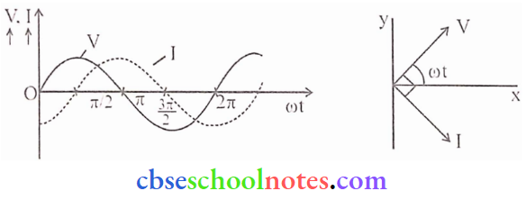
Question 1. When a pure resistance R, pure inductor L, and an ideal capacitor of capacitance C are connected in series to a source of alternating e.m.f., then-current at any instant through the three elements has the same amplitude and is represented as I = I0 sin ωt.
However, the voltage across each element has a different phase relationship with the current as shown in the graph. The effective resistance of the RLC circuit is called the impedance (Z) of the circuit and the voltage leads the current by a phase angle Φ.
A resistor of 12Ω a capacitor of reactance 14Ω and a pure inductor of inductance 0.1 H are joined in series and placed across 200 V, 50 Hz a.c. supply.
(1). What is the value of inductive reactance?
Answer:
XL = 2πfL = 2 x 3.14 x 50 x 0.1 = 31.4 Ω
(2). What is the value of impedance?
Answer:
∴ \(Z=\sqrt{R^2+\left(X_{L}-X_C\right)^2}=\sqrt{(12)^2+(31.4-14)^2}=21.13 \Omega\)
(3). What is the value of current in the circuit?
Answer:
∴ \(I=\frac{e}{Z}=\frac{200}{21.13}=9.46 \mathrm{~A}\)
(4). What is the value of the phase angle between current and voltage?
Answer:
∴ \(\tan \phi=\frac{X_L-X_C}{R}=\frac{31.4-14}{12}=1.45 \Rightarrow \phi=\tan ^{-1}(1.45)\)
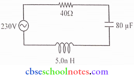
Question 2. The power averaged over one full cycle of a.c. is known as average power. It is also known as true power \(P_{\mathrm{av}}=V_{\mathrm{rms}} I_{\mathrm{rms}} \cos \phi=\frac{V_0 I_0}{2} \cos \phi\)
Root mean square or simply rms watts refer to continuous power.
A circuit containing an 80 mH inductor and a 60 μF capacitor in series is connected to a 230V, 50 Hz supply. The resistance of the circuit is negligible.
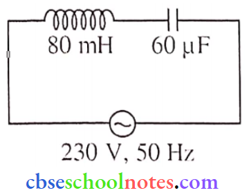
(1). What is the average power transferred to the inductor?
Answer:
Zero
(2). What is the total average power absorbed by the circuit?
Answer:
This is an LC circuit so the average power absorbed by the circuit is zero.
(3). Find the value of current amplitude.
Answer:
⇒ \(I=\frac{e}{Z}=\frac{c}{X_L-X_c}\)
e = 230 V0
XL = L = 2πfL
= 2 x 3.14 x 50 x 80 x 10-3 = 25.120 Ω
⇒ \(X_C=\frac{1}{{\omega} C}=\frac{1}{2 \pi fC}\)
∴ \(\frac{1}{2 \times 3.14 \times 50 \times 60 \times 10^{-6}}=53 \Omega\)
So, \(I=\frac{230}{53-25.120}=8.249 \mathrm{~A}\)
I0 = √2Irms
= 2 x 8.249 = 11.6 A
(4). Find the rms value of current.
Answer:
⇒ \(I=\frac{e}{Z}=\frac{e}{X_L-X_C}\)
e = 230 V0
xL = L = 2πfL
= 2 x 3.14 x 50 80 x 10-3 = 25. 120
⇒\(X_C=\frac{1}{\omega C}=\frac{1}{2 \pi f C}\)
⇒ \(\frac{1}{2 \times 3.14 \times 50 \times 60 \times 10^{-6}}=53 \Omega\)
So, \(I=\frac{230}{53-25.120}=8.249 \mathrm{~A}\)
Question 3.
- In a series LCR circuit connected to an a.c. source of voltage V = Vm sinωt, use phasor diagram to derive an expression for the current in the circuit. Hence obtain the expression tor the power dissipated in the circuit. Show that power dissipated at resonance is maximum.
- In a series LR circuit, XL = R, and the power factor of the circuit is P1. When a capacitor with capacitance C such that XL = XC is put in series, the power factor becomes P2. Calculate P1/P2.
Answer:
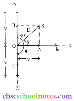
1. Suppose OA, OB, and OC represent the magnitude of phasor VR, VL, and VC respectively. In the case of VL > VC, the resultant of (VR) and (VL-VC), is represented by OE. Thus from ΔOAE
⇒ \(\mathrm{OE}=\sqrt{\mathrm{OA}^2+\mathrm{AE}^2}\)
⇒ \(V=\sqrt{V_R^2+\left(V_L-V_C\right)^2}\)
Substituting the value of VR, VL, and VC we have
⇒ \(V=\sqrt{(I R)^2+\left(I X_L-I X_C\right)^2}\)
or \(I=\frac{V}{\sqrt{(R)^2+\left(X_L-X_C\right)^2}}\)

The effective opposition offered by L, C, R to a.c. supply is called the impedance of the LCR circuit and is represented by Z.
∴ \(I=\frac{V}{Z}\)
So, comparing \(Z=\sqrt{R^2+\left(\omega L-\frac{1}{\omega C}\right)^2}\)
Also from ΔOAE
⇒ \(\tan \phi=\frac{A E}{O A}=\frac{V_L-V_c}{V_R}\)
or \(\tan \phi=\left(X_L-X_C\right) / R\)
or \(\phi=\tan ^{-1} \frac{\left(X_L-X_C\right)}{R}\)
Power dissipation in LCR circuit:
The instantaneous power supplied by the source is
P = VI
⇒ \(P=\left(V_m \sin \omega t\right) \times i_m \sin (\omega t+\phi) = \frac{V_m i_m}{2}[\cos \phi-\cos (2 \omega t+\phi)]\)
[2sinAsinB = cos(A-B)-cos(A+B)]
For Average power, the second term becomes zero in the complete cycle.
So \(P_{a v}=\frac{V_m i_m}{2} \cos \phi \quad \int_0^{\mathrm{T}} \cos (2 \omega t+\phi) d t=0\)
So \(P_{\mathrm{av}}=\frac{V_{\mathrm{m}}}{\sqrt{2}} \frac{i_{\mathrm{m}}}{\sqrt{2}} \cos \phi=V_{\mathrm{rms}} i_{\mathrm{rms}} \cos \phi\)
So \(\mathrm{P}_{\mathrm{av}}=\mathrm{V}_{\mathrm{rms}} \mathrm{i}_{\mathrm{rms}} \cos \phi\)
At resonance condition, cosΦ = 1 (because Φ) = 0), R becomes the effective impedance of a circuit. So power dissipated is maximum at resonance condition
2. In series LCR circuit impedance
⇒ \(Z=\sqrt{R^2+\left(X_L-X_C\right)^2}\) and power factor p = R/Zero
case 1: In LR circuit When XL = R, So Z = (2R2)1/2
Z = √2R = Now \(P_1=\frac{R}{Z}=\frac{R}{\sqrt{2} R} \Rightarrow P_1=\frac{1}{\sqrt{2}}\)
Case 2: XL = XC, Z=R, So power factor P2 becomes equal to 1
P2 = 1
So ration \(\frac{P_1}{P_2}=\frac{1}{\sqrt{2}}: \frac{1}{1} \Rightarrow \frac{P_1}{P_2}=\frac{1}{\sqrt{2}}\)
Question 4. A 2 μF capacitor, 100 Ω resistors, and 8 H inductor are connected in series with an AC source.
- What should be the frequency of the source such that the current drawn in the circuit is maximum, What is this frequency called?
- If the peak value of c.m.f. of the source is 200 V, find the maximum current.
- Draw a graph showing the variation of amplitude of circuit current with changing frequency of applied voltage in a series LCR circuit for two different values of resistance R1 and R2 (R1 > R2).
- Define the term ‘Sharpness of Resonance’. Under what conditions, does a circuit become
more selective?
Answer:
1. Source frequency, when current is maximum is given by
⇒ \(f=\frac{1}{2 \pi \sqrt{L C}}=\frac{1}{2 \pi \sqrt{8 \times 2 \times 10^{-6}}}\) [L = 8H and C = 2μF]
∴ \(f=\frac{1}{2 \pi \times 4 \times 10^{-3}}\)
f = 39.80 Hz
The frequency at which the current maximum, is called resonant frequency.
2. Given E0 = 200V, R= 100Ω
∴ \(I_{\max }=\frac{E_0}{R}=\frac{200}{100}=2 \mathrm{~A}\)
3. 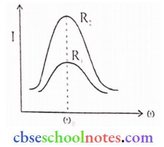
4. The sharpness of resonance is given by the quality factor (Q factor) of a resonant circuit. It is defined as the ratio of the voltage drop across the inductor (or capacitor) to the applied voltage. Sharper the curve, the circuit will be more selective. For resistant R2, the circuit is more selective.
Question 5.
- Draw a labeled diagram of a step-down transformer. State the principle and its working.
- Express the turn ratio in terms of voltages.
- Find the ratio of primary and secondary currents in terms of turn ratio in an ideal
transformer. - How much current is drawn by the primary of a transformer connected to a 220 V supply when it delivers power to a 1 10 V- 550 W refrigerator?
Answer:
1. 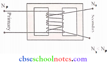
Principle: The Transformer works on the principle of mutual induction, in which an EMF is induced in the secondary coil by changing the magnetic flux in the primary coil.
Working: When an alternating current source is connected to the ends of the primary coil, the current changes continuously in the primary coil, due to which magnetic flux linked with the secondary coil changes continuously. Therefore, the alternating emf of the same frequency is developed across the secondary terminals.
2. \(\frac{N_s}{N_p}=\frac{V_s}{V_p} \quad\left\{\frac{N_s}{N_p}=\right.\text { turn ratio }\)
3. For ideal transformer
Output power = Input power
VSIS = VPIP
⇒ \(\frac{V_S}{V_p}=\frac{I_p}{I_S} \quad\left\{\frac{V_s}{V_p}=\frac{N_s}{N_p}\right.\)
∴ \(\frac{N_s}{N_p}=\frac{I_p}{I_s}\)
4. Given VP = 220 V, VS = 1 1 0 V. P = 550 W. IP = ?
⇒ \(I_p=\frac{\text { Power }}{\text { Primary Voltage }}=\frac{P}{V_p}\)
∴ \(\mathrm{I}_{\mathrm{P}}=\frac{550}{220}=2.5 \mathrm{~A}\)
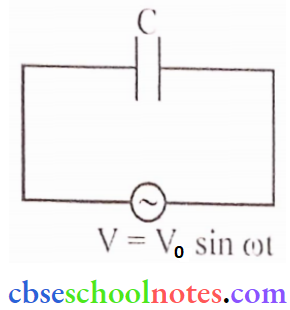
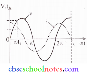
Question 6. A device ‘X’ is connected to an AC source V = V0 sin ωt. The variation of voltage, current, and power in one cycle is shown in the following graph:
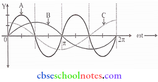
- Identify the device ‘X’.
- Which of the curves A, B, and C represent the voltage, current, and power consumed in the circuit? Justify your answer.
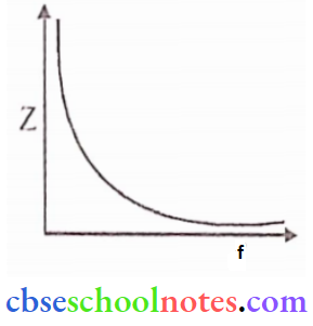
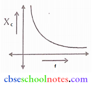
- How does its impedance vary with the frequency of the AC source? Show graphically.
- Obtain an expression for the current in the circuit and its phase relation with AC voltage.
Answer:
1. Capacitor
2. Curve: A represents power because in a pure capacitive AC circuit, power consumed in one cycle is zero and the frequency of power is twice the frequency of voltage (or current). CurvcB represents voltage. Curve-C represents current because in a pure capacitive AC circuit, current leads the voltage by π/2.
3. \(Z=X_C \Rightarrow Z=\frac{1}{2 \pi f C}\)
4. We know, \(V=\frac{q}{C} \text { or } q=C V\)
Also, q = CV0 sin t
or \(\frac{\mathrm{dq}}{\mathrm{dt}}=C \mathrm{~V}_0 \frac{\mathrm{d}}{\mathrm{dt}}(\sin {\omega} \mathrm{t})\)
I = CV0(cos ωt)
∴ \(I=\frac{V_0}{\left(\begin{array}{c}
\frac1{\omega C}
\end{array}\right)} \cos \omega t\)
\(I=\frac{V_0}{X_c} \cos {\omega} t\) (\(x_C=\frac{1}{\omega C}\))
\(I=I_0 \sin (\omega t+\pi / 2)\) \(\left[I_0=\frac{V_0}{X_C}\right]\)
∴ Leads by (π/2) with voltage.
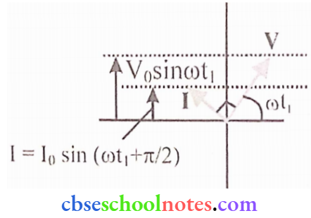
Question 7. A device X is connected across an AC source of voltage V = V0 sinωt. The current through X is given as \(I=I_0 \sin \left(\omega t +\frac{\pi}{2}\right)\)
- Identify the device X and write the expression for its reactance.
- Draw graphs showing the variation of voltage and current with lime over one cycle of ac, for X.
- How does the reactance of device X vary with the frequency of the AC? Show this variation
graphically. - Draw the phasor diagram for the device X.
Answer:
1. X: Capacitor
Reactance \(X_C=\frac{1}{\omega C}=\frac{1}{2 \pi f C}\)
2. 
3. Reactance of the capacitor varies in inverse proportion to the frequency i.e \(x_c \propto \frac{1}{f}\)
4.