
Heat Transfer In Pharmaceutical Engineering Introduction
Heat transfer is the process of transfer of heat from high high-temperature system to a low-temperature system. In terms of the thermodynamic system, heat transfer is the movement of heat across the boundary of the system due to the temperature difference between the system and the surroundings.
- The heat transfer can also take place within the system due to temperature differences at various points inside the system.
- The temperature difference is considered to be the ‘potential’ that causes the flow of heat and the heat itself is called as flux.
- There are three modes of heat transfer: conduction, convection and radiation.
- Some media is required for the transfer of heat by conduction and convection, but for radiation, no media is required.
- The process in which there is no transfer of heat between the system and its surroundings is called as adiabatic process.
- The wall or boundary which does not allows the flow of heat between the system and the surroundings is called an adiabatic wall and the wall that allows the flow of heat between the system and the surroundings is called a diathermic wall.
Heat Transfer In Pharmaceutical Engineering Objectives
- To reduce the heat or energy loss and make energy utilization more effective.
- Insulation, wherein across a finite temperature difference between the system and its surroundings, the person seeks to reduce the heat transfer as much as possible.
- Enhancement, wherein the converse of insulation, i.e. promotion of heat transfer is sought across a finite temperature difference.
- Temperature control, wherein the temperature of a region is required to be maintained close to a specified value, requires both insulation and enhancement to operate at various instances of the operational sequence of a device kept, in the region of interest.
Heat Transfer Applications In Pharmaceutical Engineering
- Evaporation: The liquid present in the material is evaporated with the help of heating to get a concentrated product.
- For example: The preparation of vegetable extracts.
- Distillation: In the distillation, two liquids are separated by the application of heating. First; the liquid having less boiling point starts to evaporate and this evaporated liquid is then condensed in a separate part of the instrument and collected.
- Drying: Removal of a small amount of moisture from a product is called as drying. Drying generally involves the direct heating or supply of hot air over the material that is to be dried,
- For example: Drying of granules in tablet processing.
- Crystallization: The saturated solution is heated to make it supersaturated which promotes the crystallization process. Further, the saturated solution can be cooled to facilitate crystallization.
- Sterilization: For sterilization purposes, the two instruments are extensively used i.e. hot air oven and autoclave. These instruments use heat to kill microorganisms.
Heat Transfer Mechanism In Pharmaceutical Engineering
Heat generally gets transferred from high-temperature regions to.
Low-temperature region by three mechanisms:
- Conduction
- Convection
- Radiation
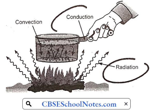
1. Conduction:
Conduction is the transfer through solids or stationary fluids. When you touch a hot object, the heat you feel is transferred through your skin by conduction.
Two mechanisms ” explain how heat is transferred by conduction:
- Lattice vibration and
- Particle collision
Conduction through solids occurs by a combination of the two mechanisms; heat is conducted through stationary fluids primarily by molecular collisions.
In solids, atoms are bound to each other by a series of bonds, analogous to springs.
- When there is a 3-temperature difference in the solid, the hot side of the solid experiences more vigorous atomic movements. The vibrations are transmitted through the springs to the cooler side of the solid.
- Eventually, they reach equilibrium, where all the atoms are vibrating with the same energy.
- Solids, especially metals, have free electrons, which are not bound to any particular atom and can freely move about the solid. The electrons on the hot side of the solid move faster than those on the cooler side.
- As the electrons undergo a series of collisions, the faster electrons give off some of their energy to the slower electrons. Eventually, through a series of random collisions, equilibrium is reached, where the electrons are moving at the same average velocity.
- Conduction through electron collision is more effective than through lattice vibration; this is why metals generally are better heat conductors than ceramic materials, which do not have many free electrons.
In fluids, conduction occurs through collisions betv/een freely moving molecules. The mechanism is identical to the electron collisions in metals.
2. Convection:
Convection uses the motion of fluids to transfer heat. In a typical convective heat transfer, a hot surface heats the surrounding fluid, which is then carried away by fluid movement such as wind.
- The warm fluid is replaced by cooler fluid, which can draw more heat away from the surface.
- Since the heated fluid is constantly replaced by cooler fluid, the rate of heat transfer is enhanced.
- Natural convection (or free convection) refers to a case where the fluid movement is created by the warm fluid itself.
- The density of fluid decreases as it is heated; thus, hot fluids are lighter than cool fluids. Warm fluids’ surrounding a hot object rise and is replaced by cooler fluid.
- The result is a circulation of air above the warm surface. Forced convection uses external means of producing fluid movement.
- Forced convection is what makes a windy, winter day feel much colder than a calm day with the same temperature.
- The heat loss from your body is increased due to the constant replenishment of cold air by the wind.
- Natural wind and fans are the two most common sources of forced convection.
3. Radiation
Radiation is a heat transfer process in which heat flows through space using electromagnetic waves.
- Radiative heat transfer occurs when the emitted radiation strikes another body and is absorbed.
- We all experience radiative heat transfer every day; solar radiation, absorbed by our skin, is why we feel warmer in the sun than in the shadow.
- The type of radiation emitted is determined largely by the temperature of the body
Heat Transfer Conduction
Heat can flow only when there is a temperature gradient, i.e. heat flows from a hot surface to a cool surface. The rate of conduction through solids can be studied easily, since it is the sole phenomenon.
The basic law of heat transfer by conduction can be written in the form of rate equation as follows:
Rate= Driving / Resistance ………………………… (1)
1. Fourier’s Law:
- The resistance term in the heat transfer equation is given by Fourier’s law. Consider an area A of a wall thickness L.
- Let the temperature be uniform over area A on one face of the wall, and uniform but lower over area A on the opposite side, then the heat flow is at right angles to the plane of A.
- Fourier’s law states that “the rate of heat flow through a uniform material is directly proportional to the area, the temperature drop, and inversely proportional to the length of the path of the flow.”
- If a small section of thickness dL, parallel to the area A is taken at some intermediate point in the wall with a temperature difference of dt across such a layer, then
Fourier’s law is represented by the following equation:
dQ / dθ = -kAdt/dL ……………………… (2)
Where k is the proportionality constant. K is known as the thermal conductivity of the solid of which the wall is made up of. The minus sign is given as temperature decreases in the direction of the flow so that dc/dt is negative. If the temperature gradient Dt/dL, does not vary with time, then the rate of heat flow is constant with time and
dQ/ dθ = Constant q = -kAdt/dL ……………………… (3)
Normally, the temperature at the two faces of the wall and not the intermediate temperature along. the path of heat transfer can be measured. The use of Fourier’s requires that the differential equation is integrated over the path from L = 0 to L = Total length.
Rearranging the above equation,
qdL/ A= -kdt …………………………………… (4)
If t is a higher temperature
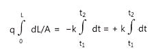 ……………………………………… (5)
The variation of k with temperature may be taken as linear, so that km, the arithmetic mean value of k may be considered constant.
dL/ A = km (t1 – t2) = km Δt
Or q= km Δt/L
By comparing the above equation with the rate equation and knowing that Δt is the driving force, L / Km A is the resistance.
Heat Transfer through a Compound Resistance in Series:
Consider a flat wall constructed of a series of layers. Let the thickness of the three layers be L1, L2, and L3 respectively. The conductivity of the materials of which the layers are made be k1, k2, and L3 and let the area of the compound wall at a plane perpendicular to the plane of illustration be A and the temperature drops across the 3 layers be Δt1, Δt2, Δt3 respectively.
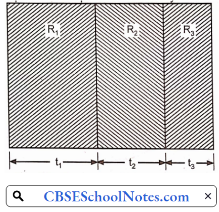
Let Δt be the temperature drop across the 3 layers then
Δt = Δt1 + Δt2 + Δt3
The equation (6) can be modified for At as
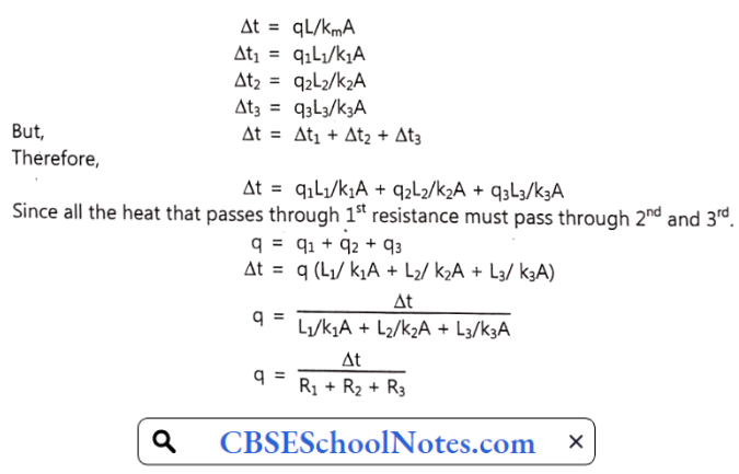
Where, R = R1, R2, R3, are resistances, the equation can be written as
Rate = Driving force / Resistance
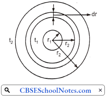
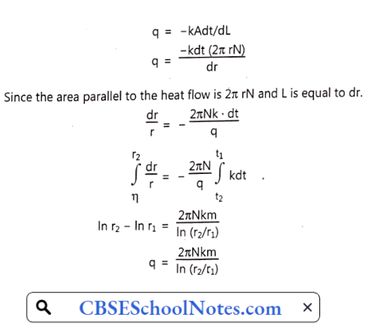
Heat Flow through a Cylinder:
Consider a cylinder with internal radius ri, outside radius r2, and length of the cylinder N. The mean thermal conductivity of the material of the cylinder is km. The temperature on the inside surface is ti and that of the outside is t2.
t1> t2 therefore heat is flowing from inside to outside. To calculate heat flow for the cylinder let us consider a very thin cylinder, concentric with a main cylinder of radius r, where r1 > r > r2, thickness of the wall is dr, dr < < < r, so that lines of heat flow may be considered parallel
Now,
Heat Transfer Convection
When fluid flow is such that the Reynolds number exceeds a certain value, the character of the flow changes from viscous to turbulent; even in turbulent flow there is at the boundary a residual film that persists in viscous flow.
The turbulence may be caused by a stirrer or agitation by pumping (forced convection) or by the natural convection currents set up when the body of fluid is heated.
- If heat is passed through the retaining wall of the fluid, the film is of great importance in determining the rate of heat transfer.
- All the heat reaching the bulk of the fluid must pass through this film by conduction.
- The thermal conductivity of the fluids is low.
- Although the film is by a stirrer or agitation by pumping (forced convection) or by the natural convection currents set up when the body of fluid is heated.
- If heat is passing through the retaining wall of the fluid, the film is of great importance in determining the rate of heat transfer, All the heat reaching the bulk of the fluid must pass through this film by conduction.
- Thermal conductivities of the fluids are low. Although the film is low, the resistances offered by the films are high.
- Beyond the film, the turbulence brings about rapid equalization of temperature.
Temperature Gradients in Forced Convection:
The temperature distribution across a column of fluid, which is in forced convection and simultaneously heated or cooled, is related to velocity distribution across the column
- Represents temperature gradients in the case where heat is flowing from a hot fluid through a metal wall into a cold fluid.
- The dotted lines F1 F1 and F2 F2 on each side of the metal wall represent the boundaries of the films in viscous flow.
- All parts of the fluid to the right of F1F1 and the left of F2 F2 are in turbulent flow.
- The temperature gradient from the bulk of the hot fluid to the metal wall is represented by the curved line ta tbtc.
- Temperature ta is the maximum temperature in the hot fluid.
- Temperature tb is the temperature at the boundary between turbulent and viscous regiments and tc is the temperature at the actual interface between fluid and solid. The significance of the line tdtetf is similar
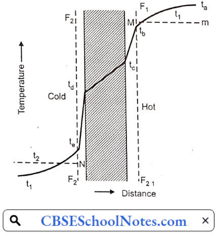
The temperature of the fluid is neither the maximum temperature tn nor minimum temperature tb at the outside surface of the film but rather the average temperature of the fluid such as that after thorough mixing of fluid and taking its temperature.
- This average temperature ti will be somewhat less than t3 and is represented by dotted line Mm and the same is true with a cold fluid whose average temperature is t2 and marked by dotted line Nn.
- If the fluid is not too viscous, or the pipe is not too large, these average temperatures are the ones that will be given when the thermometer is inserted into the pipe.
- To determine the actual course of the curve ta tbtc careful measurement with fine thermocouples is necessary.
- Temperature gradient tc td is caused by the flow of heat purely by conduction through a material whose thermal conductivity is known.
Surface Coefficients:
The indicates that the thermal resistances in the two fluids are quite complicated.
An indirect method used for their calculation involves the use of surface coefficients. In the suppose that q is the amount of heat flowing from hot fluid to cold fluid, then q must pass from hot fluid to metal wall and the same q must pass from wall to cold fluid. Let the area of the metal wall perpendicular to the direction of heat flow on the hot side be A1. The area on the cold side is A2 and the average area is Am.
The surface co-efficient on the hot side is defined by relation:
h1= q / A1(t1-t2)
= q / A1 (t1-t2)
Compared with equation q = kA Δt/L
h1 is analogous with k/L and 1/h1A1 is thermal resistance.
The thermal resistance is due to the combined effect of viscous film HH and turbulent core.
This resistance is caused by the difference in temperature ta – tb
In the same way, thermal resistance on the cold side h2 may be given by
h2 = q/ A2 (td-t2)
This can be considered as 3 resistances in series, first resistance on the hot side 1/h1A1 second thermal resistance of the metal wall L/ kAm, and third resistance on the cold side 1/h2A2. If this is substituted in the equation
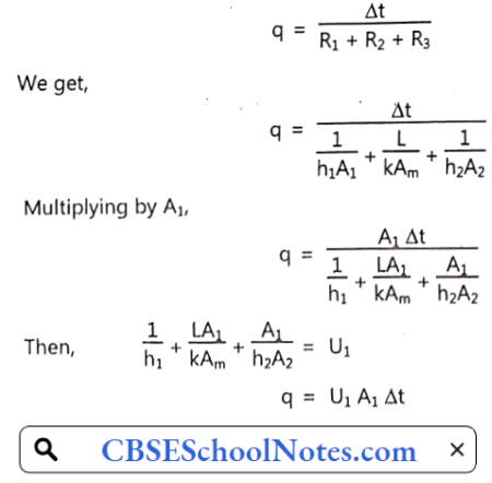
Rate of heat transfer = Over heat transfer coefficient × Area of heating surface × Temperature drop
If either of two areas, Am or A2, had been chosen, the coefficient based on these areas would be derived and denoted by Um and U2
Heat Transfer from Condensing Vapours:
When hot vapors come in contact with the surface of a lower temperature, they undergo condensation.
There are two ways by which condensation may occur:
- Film-wise condensation
- Dropwise condensation
In film condensation, condensate wets the surface by forming a continuous film over the surface. It generally occurs on clean, uncontaminated surfaces. The latent heat liberated during condensation is transferred. through the film to the surface by conduction. The thermal gradient in the film acts as resistance to heat transfer.
- In drop-wise condensation, vapor condenses into small droplets of various sizes which may grow in size or coalesce with neighboring droplets and eventually roll off the surface. under the influence of gravity.
- During drop-wise condensation, a large portion of the area of the condensing surface remains directly exposed to vapor. Therefore the rate of heat transfer is 5 to 10 times more than film-wise condensation.
- Therefore drop drop-wise condensation is preferred over film-wise condensation. But drop-wise condensation is difficult to achieve and maintain for a long time and hence in industrial equipment film film-wise condensation occurs.
- If the condensing vapor contains some noncondensable gases like air, the heat transfer coefficient decreases significantly. This is because after the condensation of vapor non-condensable gas is left at the surface which acts as a thermal resistance to the condensation process
Heat Transfer By Radiation In Pharmaceutical Engineering
Radiation may be considered as energy streaming through space at the speed of light. All substances at a temperature above absolute zero emit radiation that is independent of external agencies. This is called thermal radiation. Material may emit radiation when treated with external agencies like electron bombardment, electric discharge, etc.
- Such type of radiation does not come under thermal radiation. Radiation as such is not heat and when transformed into heat absorption it is no longer radiation.
- If the radiation is passing through space, it is not transformed into heat or any other form of energy or it is directed from its path.
- But if matter appears in its path the radiation is transmitted, reflected, and absorbed. Only the absorbed energy is quantitatively converted into heat.
- In the majority of cases, the radiant energy emitted is continuous and distributed over all wavelengths from 0 to ∞, in principle, any wavelength in the range 0 to oo be convertible heat on absorption by matter. The portion of the electromagnetic spectrum that is of importance in heat flow lies in the wavelength of 0.8 to 25 μ.
- The amount and kind of thermal energy radiated by a surface increases rapidly with temperature. When a ray of thermal radiation strikes the surface of a body a portion of incident energy may be reflected, may be absorbed, and transmitted through the body.
- The fraction of incident energy falling on a surface which is reflected by it is called reflectivity (ρ).
- The fraction of incident energy falling on a surface that is absorbed [absorptivity (α)].
- The fraction of incident energy falling on a body that is transmitted i.e. transmissivity (x).
α + τ+ ρ = 1
A body that absorbs all incident radiation falling on it is black.
α = I and τ + ρ = 0.
A black body is a theoretical substance to which all discussions refer. A black body is defined as a body that radiates the maximum possible amount of energy at a given temperature. No actual physical substance is a perfect black body.
1. Laws of Radiationl:
Kirchoff’s Law:
The emissive power of the body £ is the radiant energy emitted from the unit area in unit time. Kirchoff’s law establishes a relationship between the emissive powers of a surface to its absorptivity.
- If a small body is placed inside a large evacuated enclosure with wall temperature T, the heat will be exchanged between the body and the enclosure until equilibrium is established i.e. Enclosure wall and body will have the same temperature.
- The body will emit as much energy as it absorbs. Now, if e is the emissive power of the body, a is absorptivity and G is the rate at which energy falls from the wall of the body,
The energy balance can be given as:
G α = E
G = E/α
The rate of energy fall is the function of temperature T and the geometrical arrangement of both surfaces. But if the body is very small as compared to the enclosure and its effect upon the irradiation field of the enclosure is negligible then G remains constant at temperature.
This is stated by Kirchoff’s law that the ratio of emissive power to absorptivity is the same for all bodies in thermal equilibrium.
E1/α1 = E2/α12
Where E1 and E2 are emissive powers of the two bodies and α1 and α2 are absorptivities of the two bodies.
For a black body α = 1
Eb/1 = E/α
A = E/Eb
As the black body is a perfect radiator, it is used for the comparison of emissive powers. The ratio of emissive powers of surface to the emissive power of a black body Eb is known as emissivity
ε = E/Eb
The emissivity of the body = Absorptivity at thermal equilibrium
Although the emissivity of the surface varies with the wavelength for certain materials, it is a constant fraction of the emissive power of perfectly black body Eb therefore E/Eb is constant. Such materials that have constant emissivity are known as grey bodies. For grey bodies, the two bodies don’t have to be in thermal equilibrium to apply Kirchoff’s law.
Stefan-Boltzmann Law:
Stefan-Boltzmann law states that the emissive power of the black body is proportional to the fourth power of absolute temperature.
q = bAT4
Where
q = Energy radiated per hour
A = Area of radiating surface
T = Absolute temperature of radiating surface
b = Constant
No actual body radiates as much as a black body. It can be expressed as,
q = ε bAT4
Where e is the emissivity of the body.
Consider a small black body of area A and temperature T2, completely surrounded by a hotter black body of temperature T1. The net amount of heat transferred from the hotter body to the colder body is, therefore, the algebraic sum of radiation from the two bodies
So Stefan Boltzmann’s law is written as:
q = bAT41 – T41
Heat Exchangers And Heat Interchangers In Pharmaceutical Engineering
Most pharmaceutical and chemical industries use a variety of heat transfer equipment.
The heating media may be hot fluid or condensed steam.
- Heat exchangers: Heat exchangers are devices used for transferring heat from one fluid (gas or steam) to another fluid (liquid) through a metal wall.
- Heat interchangers: Heat interchangers are the devices used for transferring heat from one liquid to another or from one gas to another through a metal wall.
1. Heat Exchangers:
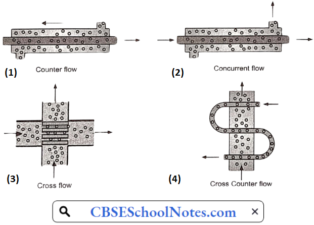
Classification of Heat Exchangers by Flow Configuration:
There are four basic flow configurations
- Counter Flow.
- Concurrent Flow.
- Cross Flow.
- Hybrids such as Cross Counterflow and Multi-Pass Flow.
Classification based on construction:
- Shell and Tube Heat Exchanger.
- Plate Heat Exchanger.
- Regenerative Heat Exchanger.
- Adiabatic Wheel Heat Exchanger.
Equipments:
1. Shell and tube heat exchanger (tubular heater):
The shell and tube heat exchanger is made up of a bundle of parallel heat exchanger tubes held in place with tube sheets and placed into a shell.
- The heat exchange always takes place between two fluids through the heat exchanger tube wall.
- There are quite a variety of flow options for shell and tube heat exchangers. In all of the configurations for shell and tube heat exchangers, one fluid passes through the tubes (the tube side fluid) and the other passes through the shell (the shell side fluid).
- The choice of shell and tube heat exchanger configuration affects the overall heat transfer coefficient and thus also affects the rate of heat transfer and the heat exchanger tube surface area needed.
- Important components of a shell and tube heat exchanger in addition to tubes (can be U-tube or straight tube) and shell are the tube sheets, baffles, end channels for the tube side fluid, and inlet and outlet nozzles for both the shell side fluid and the tube side fluid.
- The tube sheets serve to hold the tubes in place in a “tube bundle” and also can serve as baffles to create turbulence and a more consistent residence time for the shell side fluid.
- The end channels distribute the tube-side fluid and create either a transition to the outlet nozzle or a means to send the tube-side fluid back to the other end of the heat exchanger.
A straight-tube heat exchanger is easier to clean than a U-tube heat exchanger, so it is better for a tube-side fluid that tends to foul the tube, causing a need for regular cleaning. The U-tube heat exchanger works well if the two fluids have greatly different thermal expansion characteristics because it can allow the tube and the shell to expand or contract independently.
Number of passes:
The number of passes refers to the tube side fluid. The shell and tube heat exchanger is commonly made in single-pass, two-pass, and four-pass configurations, although custom multipass heat exchangers with yet another number of passes are also available
Tubular Heater Advantage:
A large heating surface can be packed in a small area.
Tubular heater Disadvantages:
- The velocity of liquid flowing in these tubes is low.
- The expansion of tubes takes place due to differences in temperatures. This may lead to loosening of the tube sheets.
2. Floating head heater:
The expansion of the tubes due to temperature differences is the problem of tubular heaters. To overcome this problem some modifications have been done in the design of it. It is called a floating head heater. To make easy removal of the tube bundles possible and to allow for considerable expansion of the tubes, a floating head exchanger is used. In this, exchanger tubes are fixed at both the ends of the floating and stationary tube sheets. The stationary tube sheet is clamped between shells
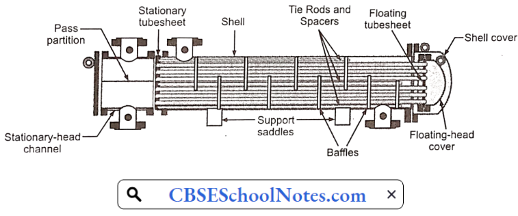
The floating tube sheet is clamped between the floating head and a clamp ring. The ring which is split in half to permit dismantling is placed at the back of the tube sheet and shows the details of a split ring assembly. The floating tube sheet is kept slightly smaller in diameter than the inside diameter of the shell to withdraw the entire tube bundle from the channel end. The channel is provided with an inlet and outlet connection for tube-side fluid. The shell is closed by a shell cover or bonnet on a floating head side.
The shell cover at the floating head end is larger than the other end to enable the tubes to be placed as near as possible to the edge of the fixed tube sheet. The tube sheet along with the floating head is free to move and take the differential thermal expansion between the shell and the tube bundle.
Floating head heater Types:
- Internal floating head
- With clamp ring
- Without clamp ring
- External floating head
Floating head heater Applications:
- Used as steam superheaters
- Phase change units (Reboilers)
Floating head heater Advantages:
- The tubes of the exchanger are removable for inspection and mechanical cleaning of the outside of the tubes.
- It eliminates differential expansion problems.
- The heat exchanger can be operated under high temperature and high pressure, the average temperature is less than or equal to 450°C, and the pressure is less than or equal to 6.4 MPa.
2. Heat Interchangers
The heating medium is a hot liquid which heats a cold liquid. Film coefficients of both inside and outside the tube are nearly of the same magnitude and the value of the overall heat transfer coefficient is nearer to the smaller of the two coefficients.
- Film coefficients can be enhanced by increasing the velocity of the flow of both fluids. It is difficult to increase the velocity of fluid outside the tubes.
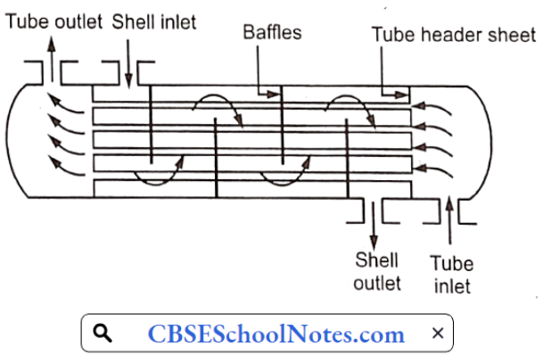
- However, the surface area of contact can be increased by introducing baffles. Baffles consist of circular discs of sheet metal with one side cut away.
- They are perforated to receive the tubes. Baffles are supported by one or more guide rods, which are fastened between tubes by sheets.
- They are placed outside the tube. They increase the surface area of contact for liquid outside the tube and. make the liquid flow more or less at right angles to a tube which creates more turbulence.
1. Liquid to liquid heat interchanger:
The construction of a liquid-to-liquid heat interchanger is shown in the figure. Usually, tube sheets and baffles are assembled first then tubes are installed.
- Baffles are arranged in the proper place by using short sections of the same tube.
- The ends of the tubes are expanded into tube sheets.
- The entire assembly is enclosed in a shell. Shell has a provision for introducing a heating medium i.e., hot fluid. On each side of the tubes, two distribution chambers are provided. The left side chamber contains an inlet for fluid to be heated.
- The outlet for heated fluid is provided at the center of the right-side distribution chamber.
- Hot fluid is pumped from the left side top of the shell. Fluid flows outside the tubes and moves down to the bottom. Then it changes in direction and rises.
- This is continued till it leaves the heater. Baffles lengthen the path and increase the cross-section of the path.
- Liquid to be heated is pumped through the inlet provided on the left side distribution chamber. It flows through the tube and heated liquid is collected through the tube in a single pass.
- Heated liquid is collected on the right side distribution chamber.
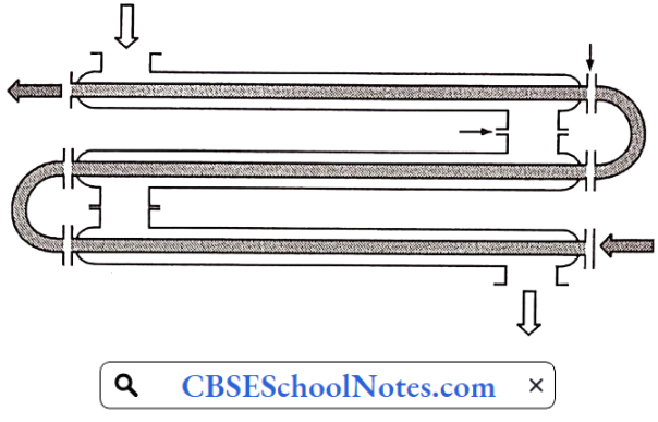
2. Double pipe heat interchangers:
Where conditions are such that the relation between the volume of liquid inside tubes, the velocity desired and the size of the tube desired results in only a few tubes per pass, the simplest construction is the double pipe heat interchanger.
- One liquid flows through the inside of the pipe and the second liquid flows through the annular space between the pipes.
- These are primarily used for low flow rates, high-temperature drops, and high-pressure applications because of their relatively small pipe diameters.
- Outer pipe size varies from 2 to 4 inches with inner tubes varying from 3/4 to 2.5 inches in size.
- Some have longitudinal fins on the outside of the inner tube. Standard double-pipe sections with removable tubes and with provision for differential expansion between outer and inner tubes are commercially available.
- Counter-current flow in these interchangers is advantageous when very close temperature approaches are required.
- Multiple double pipe sections are also available with 8 and 16-inch outer pipe sections. Double pipe exchangers are also available in glass and impervious graphite constructions.
Heat Transfer In Pharmaceutical Engineering Multiple-Choice Questions
Question 1. When heat is transferred by molecular collision, it is referred to as heat transfer by
- Conduction
- Convection
- Radiation
- Scattering
Answer: 1. Conduction
Question 2. When heat is transferred from a hot body to a cold body in a straight line, without affecting the intervening medium, it is referred to as heat transfer.
- Conduction
- Convection
- Radiation
- Conduction and convection
Answer: 3. Radiation
Question 3. When heat is transferred from one particle of a hot body to another by the actual motion of the heated particles, it is referred to as heat transfer by _____________
- Conduction
- Convection
- Radiation
- Conduction and convection
Answer: 1. Conduction
Question 4. In radiative heat transfer, a gray surface is one _____________
- Which appears gray to the eye.
- Whose emissivity is independent of wavelength.
- Which has reflectivity equal to zero.
- Which appears equally bright from all directions.
Answer: 2. Whose emissivity is independent of wavelength.
Question 5. Heat transfer takes place according to _____________
- First Law of Thermodynamics.
- Second Law of Thermodynamics.
- Third Law of Thermodynamics.
- Zeroth Law of Thermodynamics.
Answer: 2. Second Law of Thermodynamics.
Question 6. Fourier law of heat conduction is based on the assumption that_____________
- Heat flow through a solid is one-dimensional.
- Heat flow is in a steady state.
- Both (1) and (2).
- None of the options.
Answer: 3. Both (1) and (2).
Question 7. To which type of heat flow Fourier’s law is applicable?
- Conduction
- Convection
- Radiation
- Conduction and convection
Answer: 1. Conduction
Question 8. The flow of heat does not apply to_____________
- Centrifugation
- Crystallization
- Drying
- Refrigeration
Answer: 1. Centrifugation
Question 9. Drop-wise condensation of steam is possible in one of the following conditions of the pipe?
- Clean surface
- Rough surface
- Greasy surface
- Smooth surface
Answer: 3. Greasy surface
Question 10. Which equipment causes the heat transfer by radiation?
- Hot air oven
- Incubator
- Micro
- Refrigerator
Answer: 3. Micro