
Flow Of Fluids in Pharmaceutical Engineering Introduction
A substance that takes the shape of its container and flows from one location to another is called a fluid. The class of all materials that are fluids includes both liquids, such as water, and gases, such as air. The class of incompressible fluids is called liquids.
- Fluid flow is a part of fluid mechanics that deals with dynamics. Fluids such as gases and liquids in motion is called fluid flow.
- Fluid flow is an important aspect in various pharmaceutical industry processes, including large production-scale equipment applications, flows in laboratory devices used to analyze and develop drugs, and biological transport in the human body.
- To improve the development, production, analysis, and delivery of new therapies, efficient tools are needed to characterize, understand, and ultimately predict flow in relevant systems.
- Several factors motivate an improved understanding of these flows. Even more complex synthesis of drugs, tighter regulatory requirements, and the development of novel drug delivery systems involve increasingly sophisticated fluid flow.
- Fluid motion can affect several steps needed to produce a pharmaceutical product, thus highlighting the need to advance the study of fluid flows throughout the industry.
- Fluids can flow steadily, or be turbulent. In steady flow, the fluid passing through a given point maintains a steady velocity.
- For turbulent flow, the speed and or the direction of the flow varies. In steady flow, the motion can be represented with streamlines showing the direction the water flows in different areas. The density of the streamlines increases as the velocity increases fluids can be compressible or incompressible.
This is the big difference between liquids and gases, because liquids are generally incompressible, meaning that they don’t change volume much in response to a pressure change whereas gases are compressible, and will change volume in response to a change in pressure. Fluid can be viscous (pours slowly) or non-viscous (pours easily)
Laminar flow and turbulent flow:

Flow Of Fluids Manometers
A manometer is a device for measuring fluid pressure consisting of a bent tube containing one or more liquids of different densities. A known pressure (which may be atmospheric) is applied to one end of the. manometer tube and the unknown pressure (to be determined) is applied to the other end
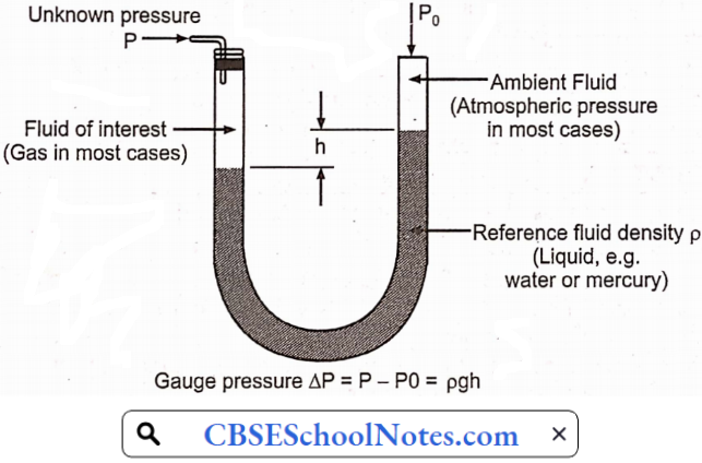
Manometer operates on the hydrostatic balance principle. A basic manometer includes a reservoir filled with a liquid. The reservoir is usually enclosed with a connection point that can be attached to a source to measure its pressure. A transparent tube or column is attached to the reservoir.
- The top of the column may be open, exposing it to atmospheric pressure, or the column may be sealed and evacuated.
- Manometers that have open columns are usually used to measure gauge pressure or pressure about atmospheric pressure.
- Manometers with sealed columns are used to measure absolute pressure or pressure about absolute zero.
- Manometers with sealed columns are also used to measure vacuum.
- When a manometer is connected to a process, the liquid in the column will rise or fall according to the pressure of the source.
- It will, get measured. To determine the amount of pressure, it is necessary to know the type of liquid in the column, and the height of the liquid.
- The type of liquid in the column of a manometer will affect how much it rises or falls in response to pressure, its specific gravity must be known to accurately measure pressure.
- Manometers are accurate; they are often used as calibration standards.
- The shape of the liquid at the interface between the liquid and air in the column affects the accuracy of the manometer. This level is called the meniscus.
- The shape of the meniscus is determined by the type of liquid used.
- To minimize the errors that result from the shape of the meniscus, the reading must be taken at the surface of the liquid in the center of the column.
- The quality of the fill liquid will also affect the accuracy of pressure measurements. The fill liquid must be clean and have a known specific gravity.
Manometer Classification
Broadly manometers are classified into two classes
- Simple manometer: Simple manometers are those that measure pressure at a point in a fluid contained in a pipe or a vessel.
- Simple manometers are of many types:
- Piezometer
- U-tube manometer
- Single column manometer
- Simple manometers are of many types:
- Differential manometer: Differential manometers measure the difference of pressure between any two points in a fluid contained in a pipe or vessel.
- The differential manometer is of the following types:
- U-tube differential manometer
- Inverted U-tube differential manometer: This type of manometer is used for measuring the difference between two pressures (where accuracy is a major consideration).
- The differential manometer is of the following types:
1. Inclined manometer
1. Piezometer:
A piezometer is one of the simplest forms of manometer. It can be used for measuring the moderate pressure of liquids.
- The setup of the piezometer consists of a glass tube, inserted in the wall of a vessel or of a pipe.
- The tube extends vertically upward to such a height that liquid can freely rise in it without overflowing.
- The pressure at any point in the liquid is indicated by the height of the liquid in the tube above that point.
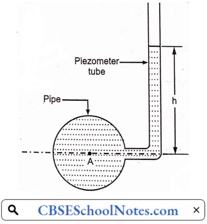
Pressure at point A can be computed by measuring the height to which the liquid rises in the glass tube.
The pressure at point A is given by:
⇒ p = wh,
Where w is the specific weight of the liquid.
Limitations of Piezometer:
- Piezometers can measure gauge pressures only. It is not suitable for measuring negative pressures
- Piezometers cannot be employed when large pressure in lighter liquids is to be measured since this would require very long tubes, which cannot be handled conveniently.
- Gas pressure cannot be measured with piezometers, because a gas forms no free
atmospheric surface.
2. U-tube manometer:
The piezometer cannot be employed when large pressure in the lighter liquids is to be measured, since this would require very long tubes, which cannot be handled conveniently. Furthermore, gas pressure cannot be measured by the piezometers because a gas forms no free atmospheric surface.
These limitations can be overcome by the use of U-tube manometers.
- A U-tube manometer consists of a glass tube bent in a U-shape, one end of which is connected to a point at which pressure is to be measured and the other end remains open to the atmosphere.
- Using a “U’ Tube enables the pressure of both liquids and gases to be measured with the same instrument.
- The “U” is filled with a fluid called the manometric fluid.
- The fluid whose pressure is being measured should have a mass density less than that of the manometric fluid.
Characteristics of liquid used in U-tube Manometer:
- Viscosity should be low.
- Low surface tension is required.
- The liquid should stick to the walls.
- Should not get vaporized.
- The two fluids should not be able to mix readily that is, they must be immiscible.
U-tube Manometer Advantages:
- Simple in construction.
- Low cost hence easy to buy.
- Very accurate and sensitive.
- It can be used to measure other process variables.
U-tube Manometer Disadvantages:
- Fragile in construction
- Very sensitive to temperature changes
U-tube Manometer Applications:
- It is used for low-range pressure measurements.
- Extensively used in laboratories.
- Is used in orifice meters and venturi meters for flow measurements.
- It is used for the calibration of gauges and other instruments.
- It is used for measuring pressure drops in different joints and valves.
3. Single-column manometer (micromanometer):
The U-tube manometer described above usually requires the reading of fluid.
- Levels at two or more points since a change in pressure causes a rise of the liquid in one limb of the manometer and a drop in the other.
- This difficulty is however overcome by using single-column manometers.
- A single-column manometer is a modified form of a U-tube manometer in which a shallow reservoir having a large cross-sectional area (about 100 times) as compared to the area of the tube is connected to one limb of the manometer,
Single Column Manometer Advantages:
- Easy to fabricate and relatively inexpensive.
- Good accuracy.
- High sensitivity.
- Requires little maintenance.
- Not affected by vibrations.
- Specially suitable for low pressure and low differential pressures.
- It is easy to change the sensitivity by affecting a change in the quantity of manometric liquid in the manometer.
Limitations of Single Column Manometer:
- Usually bulky and large.
- Being fragile, gets broken easily.
- Readings of the manometer are affected by changes in temperature, altitude, and gravity.
- A capillary effect is created due to the surface tension of the manometric fluid.
2. Differential manometer
The differential manometer measures the difference of pressure between any two points in a pipe containing fluid. These are used to measure small pressure differences. It can also measure small gas pressures (heads). These manometers have extreme precision and sensitivity. These are free from errors due to capillarity and require no calibrations
Types of Differential Manometer:
The principle and working of the types of differential manometers are given below
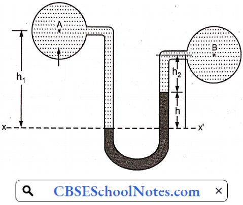
U-tube Differential Manometer:
In the adjoining figure, the two points A and B are in liquids having different specific gravity. Also, A and B are at different levels. A liquid that is denser than the two fluids is used in the U tube, which is immiscible with the other fluids. Let the pressure at point A be PA and that at point B be PB.
PA – PB = 9 x h (ρg – ρ1)
Where
h = Difference in mercury level in the U-tube
ρg = Density of heavy liquid
ρ1 = Density of liquid A
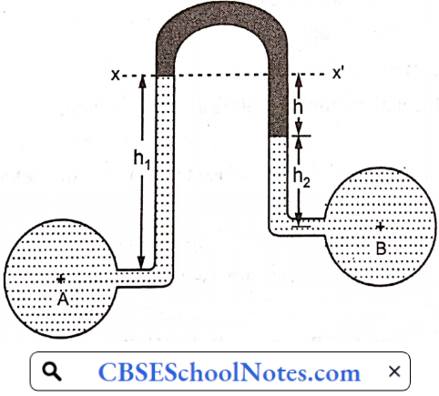
Inverted U-tube Differential Manometer:
This type of manometer is used when the difference between the densities of the two liquids is small.
- Similar to the previous type, A and B are points at different levels with liquids having different specific gravity.
- It consists of a glass tube shaped like an inverted letter ‘U’ and is similar to two piezometers connected end to end.
- Air is present at the center of the two limbs. As the two points in consideration are at different pressures,
- The liquid rises in the two limbs.
- Air or mercury is used as the manometric fluid.
If PA is the pressure at point A and PB is the pressure at point B:
PA-PB = ρ1 × g × h1 -ρ2 × g × h1 × ρg × g × h
ρ1 = Density of liquid at A
ρ2 = Density of liquid at B
ρg = Density of light liquid
h = Difference of light liquid
Where,
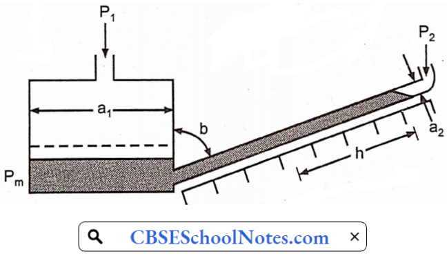
3. Inclined Type Manometer
It is similar to a well-type manometer in construction. The only difference is that the vertical column limb is inclined at an angle of 0. Inclined manometers are used for accurate measurement of small pressure.
Flow Of Fluids Bernoulli’s Theorem
When the principle of conservation of energy is applied to the flow of fluids, the resulting equation is called Bernoulli’s theorem.
- Bernoulli’s theorem is only a special case of the law of conservation of energy.
- Bernoulli’s theorem states that in a steady state ideal flow of an incompressible fluid.
- The total energy per unit mass, which consists of pressure energy, kinetic energy and datum energy, at any point of the liquid is constant.
- In simple terms, an increase in the velocity of fluid is compressed by a decrease of pressure.
- In most cases, the temperature in the fluid decreases as the fluid moves faster. Consider a system represented.
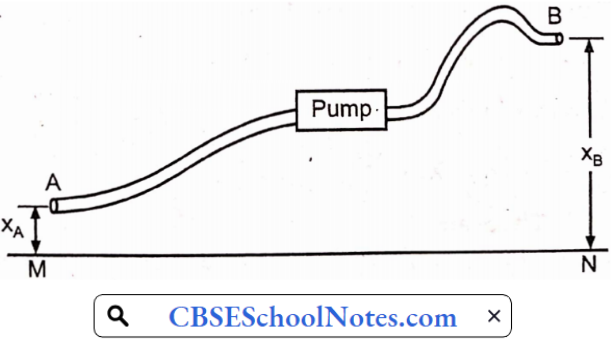
- It represents a pipe transferring a liquid from point A to point B. The pump supplies the energy to cause the flow. Consider that 1 lb liquid enters at point A. Let the
- Pressure at point A be PA lb force/sq.ft, let the average velocity of liquid be PA fps and let the specific volume of liquid be VA Cu ft/lb.
- Line MN represents the horizontal datum plain. Point A and B are at a height XA and XB respectively from the datum plane.
- The potential energy of a pound of liquid at A has potential energy equal to XA ft-lb. The velocity of the liquid is XA ft-lb the kinetic energy of the liquid = U2A ft-lb/ 2gc.
- A pound of liquid enters the pipe against a pressure PA lb force/ sq.ft.
- Therefore work done on a pound of liquid equal to PA VA ft lb is added to the energy. The total energy of the system is the sum of all the three energies.
Total energy = Potential energy + Kinetic energy + Pressure energy
The total energy of 1 lb of liquid at A ⇒ XA +U2A/2gc + PAVA
After a steady state when one pound of liquid enters at point A another pound is displaced at B, according to the principle of conservation of mass. It will have energy
⇒ XB +U2B/2gc + PBVB
Where UB, PB, and VB are velocities, pressure, and specific volume respectively at point B.
If there are no additions or losses the energy content of one pound of liquid entering at A is exactly equal to its energy at B, according to principles of conservation of energy
⇒ XA +U2B/2gc + PBVB + PAVA
= XB +U2B/2gc + PBVB
But some energy is added by the pump. Let this be equal to w ft. lb per lb of liquid. Some energy is lost due to friction. Let this be equal to F ftlb/lb of liquid. The energy balance may be completely represented by the following equation:
⇒ XA +U2A/2gc + PAVA – F + w = XB + PBVB
If density of liquid is ρ lb/ft³ then VA = l/pA and VB = l/pB
⇒ XA +U2A/2gc +PA / ρA – F + w = XB +U2B/2gc +PA / ρB
Bernoulli’s Theorem Application:
- One of the most common everyday applications of Bernoulli’s principle is in air flight
- The main way that Bernoulli’s principle works in air flight has to do with the architecture of the wings of the plane.
- In an airplane wing, the top of the wing is somewhat curved, while the bottom of the wing is flat.
Bernoulli’s theorem states the “total energy of a liquid flowing from one point to another remains constant” It applies to non-compressible liquids
- Airflight
- Lift
- Baseball
- Drafy
- Sailing
Flow Of Fluids Reynolds Number
The Reynolds number is the ratio of inertial forces to viscous forces within a fluid that is subjected to relative internal movement due to different fluid velocities. The Reynolds number quantifies the relative importance of these two types of forces for given flow conditions and is a guide to when turbulent flow will occur in a particular situation.
Reynolds number gives information about the flow of fluids and indicates whether its flow of fluid is laminar or turbulent.
- Laminar flow occurs at low Reynolds numbers, where viscous forces are dominant, and is characterized by smooth, constant fluid motion.
- Turbulent flow occurs at high Reynolds numbers and is dominated by inertial forces, which tend to produce chaotic eddies, vortices, and other flow instabilities.
If Re < 2100, flow is laminar.
For Re > 4000, flow is turbulent.
For 2100 < Re < 4000, flow- is in transition from laminar to turbulent

Reynolds number can be determined by using the following formula:
R = Inertial force/ viscous force
R = ρυD/μ
- R is the Reynolds number
- ρ is the fluid density in kilograms-per-cubic-meter (kg/m3).
- v is the velocity in meters-per-second (m/s).
- D is the diameter of the pipe in meters (m).
- μ is the viscosity of the fluid in pascal-seconds (Pa s).
- Reynolds number can also be expressed as
R = Inertial force/Viscous forces
= Mass × Acceleration of liquid flowing / Shear stress × Area
Significance of Reynolds Number Applications:
- Reynolds number plays an important part in the calculation of the friction factor in a few of the equations of fluid mechanics, including the Darcy-Weisbach equation
- It is used when modeling the movement of organisms swimming through water.
- Atmospheric air is considered to be a fluid. Hence, the Reynolds number can be calculated for it.
- This makes it possible to apply it in wind tunnel testing to study the aerodynamic properties of various surfaces.
- Reynolds number is used to predict the nature of flow during the experiment.
- Turbulent flow chromatography is often used for on-line sample cleanup of biological matrices in liquid chromatography-mass spectrometry applications
Flow Of Fluids Energy Losses During Fluid Flow
When a fluid is flowing through a pipe, the fluid experiences some resistance due to which some of the energy of the fluid is lost. This loss of energy is classified as:
Major Energy Losses
- Frictional Losses in Laminar Flow:
- Darcy’s equation can be used to find head losses in pipes experiencing laminar flow by noting that for laminar flow,
- The friction factor equals the constant 64 divided by the Reynolds number
- f = 64/Re
- Substituting this into Darcy’s equation gives the Hagen-Poiseuille equation → HL = 64/ Re [L/D][v2/2g]
- Frictional Losses in Turbulent Flow:
- Darcy’s equation can be used to find head losses in pipes experiencing turbulent flow.
- However, the friction factor in turbulent flow is a function of the Reynolds number and the relative roughness of the pipe.
- Effect of Pipe Roughness:
- The relative roughness of pipe is defined as the ratio of inside surface roughness (s) to the diameter
- Relative roughness = ε/ D
Minor Energy Losses
The loss of energy due to a change of velocity of the flowing fluid in magnitude or direction is called minor loss of energy. The minor loss of energy includes the following cases:
1. Energy Losses in Bends and Fittings:
When the direction of flow is altered or distorted, as when the fluid is flowing round bends in the pipe or through fittings of varying cross-sections, energy losses occur which are not recovered.
- This energy is dissipated in eddies and additional turbulence and finally lost in the form of heat.
- However, this energy must be supplied if the fluid is to be maintained in motion, In the same way, as energy must be provided to overcome friction.
- Losses in fittings have been found, as might be expected, to be proportional to the velocity head of the fluid flowing.
- In some cases, the magnitude of the losses can be calculated but more often they are best found from tabulated values based largely on experimental results.
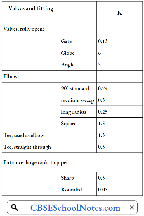
- The energy loss is expressed In the general form,
Ef = kV²/2
Where V is the velocity of the fluid, k has to be found for the particular fitting. Values of this constant k for some fittings are given in Table
Friction loss factors in fittings
Energy is also lost at sudden changes in pipe cross-section. At a sudden enlargement, the loss is equal to
⇒ Ef = (v1-v2)²/2
For a sudden contraction
Ef = kV²/2
Where v1 is the velocity upstream of the change in section and v1 is the velocity downstream of the change in pipe diameter from D1 to D2.
The coefficient k in the equation depends upon the ratio of the pipe diameters (D2/D1) as given in Table
Loss factors in contractions:

2. Sudden expansion of pipe:
The head due to the sudden expansion equation is the (V1-V2)/2g
Where V1 is the velocity at the section 1
V2 is the velocity in section 2
3. Sudden contraction of pipe:
The head loss due to the sudden contraction equation is
hc = k(V²2/2g)
Where k= [(1/Cc)-1]²
V2 is the velocity in section 2
Flow Of Fluids Measurement Of Rate
Pitot Tube
A Pitot tube, also known as a Pitot probe, is a pressure measurement instrument used to measure fluid flow velocity.
- The pitot tube was invented by the French engineer Henri Pitot in the early 18th century and was modified to its modern form in the mid-19th century by French scientist Henry Darcy.
- It is widely used to determine the airspeed of an aircraft, and the water speed of a boat, and to measure liquid, air, and gas flow velocities in certain industrial applications.
- The pitot tube is used to measure the local flow velocity at a given point in the flow stream and not the average flow velocity in the pipe.
Pitot Tube Construction:
It is a fluid velocity measuring instrument that can also be used for flow measurement of liquids and gases.
- It consists of two hollow tubes that sense pressure at different places within the pipe.
- These hollow tubes can be mounted separately in a pipe or installed together in one casing as a single device.
- One tube measures the. stagnation or impact pressure and another tube measures only static pressure usually at the wall of the pipe
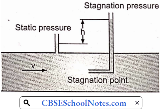
Pitot Tube Principle:
When a solid body is kept centrally, and stationary in a pipeline with flowing fluid.
- The velocity of the fluid starts reducing (at the. same time the pressure fluid increases due to the conversion of kinetic energy into pressure energy) due to.
- Presence of the body. Directly in front of the solid body, the velocity becomes zero. This point is known as the stagnation point.
- The fluid flow can be measured by measuring the differences between the pressure at the normal flow line (static pressure) and the stagnation point (stagnation pressure).
Pitot Tube Working:
The liquid flows up the tube and when equilibrium is attained, the liquid reaches a height above the free surface of the water stream.
- Since the static pressure, under this situation, is equal to the hydrostatic pressure due to its depth below the free surface:
- The difference in level between the liquid in the glass tube and the free surface becomes the measure of dynamic pressure.
The equation of velocity is derived by applying Bernoulli’s principle; the final equation is given below:
Velocity , υ= \(\sqrt{(2gh)}\)
g = Acceleration due to gravity
Actual velocity = Cυ \(\sqrt{(2gh)}\)
Pitot Tubes Advantages:
- Economical to install.
- Does not contain moving parts; this minimizes the frictional loss.
- Easy to install due to its small size. It can introduce fluid flow without shutting down the flow.
- The loss of pressure is very small.
- Can be easily installed in extreme environments, high temperatures, and pressure conditions.
Pitot Tubes Disadvantages:
- Low sensitivity and poor accuracy. It requires high-velocity flow.
- Not suitable for dirty or sticky fluid like sewage disposal.
- Sensitivity disturbed by the flow direction
- Pitot tubes have found limited applications in industries because they can easily become clogged with foreign materials in the liquid.
- There is no standardization for pitot tubes.
Change in velocity profile may cause significant errors. Due to a change in velocity profile, it develops a very low differential pressure which is difficult to measure.
Venturi meter
Venturi meter Principle:
A venturi meter is an example of a restriction-type flow meter.
- Its work is based on Bernoulli’s principle. In Venturimeter, Pressure energy (PE) is converted into Kinetic Energy (KE) to calculate the flow rate (discharge) in a closed pipeline.
- When a venturi meter is placed in a pipe carrying the fluid whose flow rate is to be measured, a pressure drop occurs between the entrance and the throat of the venturi meter.
- This pressure drop is measured using a differential pressure sensor and when calibrated this pressure drop becomes a measure of flow rate.
Venturi meter Construction:
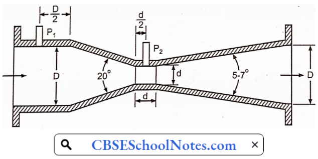
Above the general dimensions of a Herschel standers type venturimeter.
It consists of three parts:
- Converging inlet or inlet cone
- Throat
- Divergent cone or outlet cone.
Venturimeter is usually made of cast iron, bronze, or steel. The converging part is made shorter by employing a large cone angle (19° – 21°) while the diverging section is longer with a lower cone angle (5°-15°). The high-pressure tap is located at starting of the Venturi and the low-pressure tap is located in the middle of the throat sections. The accuracy of this type of flow meter ranges from ± 0.25% to ± 3%
Venturi meter Working:
The venturi meter is used to measure the rate of flow of fluid flowing through the pipes. Here we have considered two cross-sections, the first at the inlet and the second one at the throat.
- The difference in the pressure heads of these two sections is used to calculate the rate of flow through the venturimeter.
- As the water enters the inlet section i.e. in the converging part it converges and reaches the throat.
- The throat has a uniform cross-section area and the least cross-section area in the venturimeter.
- As the water enters the throat its velocity increases and due to an increase in the velocity the pressure drops to the minimum.
- Now there is a pressure difference of the fluid at the two sections.
- In section 1 (i.e. at the inlet) the pressure of the fluid is maximum and the velocity is minimum.
- In section 2 (at the throat) the velocity of the fluid is maximum and the pressure is minimum.
- The pressure difference at the two sections can be seen in the manometer attached at both sections.
- This pressure difference is used to calculate the rate flow of a fluid flowing through a pipe.
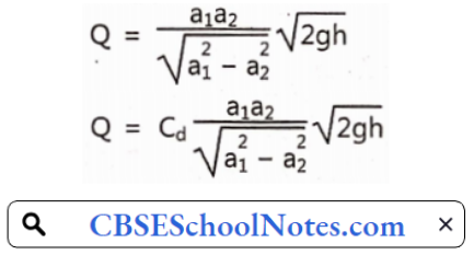
a1, a2 = Area of cross-section at inlet and throat.
g = Acceleration due to gravity
h = Pressure head difference
Cd = Coefficient of discharge
Venturi meter Uses:
- Venturimeter is used in a wide variety of applications that include gas, liquids, slurries,’ suspended oils, and other processes where the permanent pressure loss is not tolerable.
- It is widely used in large-diameter pipes such as found in the waste treatment process.
- It allows solid particles to flow through it because of their gradually sloping smooth design; so they are suitable for the measurement of dirty fluid.
- It also.is used to measure fluid velocity.
Venturi meter Advantages:
- High-pressure recovery. Low permanent pressure drop.
- High coefficient of discharge.
- Smooth construction and low cone angle help the solid particles flow through it.
- So it can be used for dirty fluids.
- It can be installed in any direction horizontal, vertical or inclined.
- More accurate than the orifice and flow nozzle.
Venturi meter Disadvantages :
- Size as well as cost is high.
- Difficult to inspect due to its construction.
- Nonlinear.
- For satisfactory operation, the venturi must be proceeded by long straight pipes.
- Its maintenance is not easy.
- It cannot be used in a pipe that has a small diameter (70mm).
Orifice Meter
An Orifice Meter is a type of flow meter used to measure the rate of flow of liquid or gas, especially steam, using the Differential Pressure Measurement principle.
- It is mainly used for robust applications as it is known for its durability and is very economical.
- As the name implies, it consists of an Orifice plate which is the basic element of the instrument.
- When this Orifice plate is placed in a line, a differential pressure is developed across the Orifice plate.
This pressure drop is linear and is in direct proportion to the flow rate of the liquid or gas.
Orifice Meter Principle:
- When a liquid/gas, whose flow rate is to be determined, is passed through an Orifice meter, there is a drop in the pressure between the INLET section and outlet section of the Orifice meter.
- This pressure drop can be measured using a differential pressure measuring instrument (The working principle of an Orifice meter is the same, as that of a venturi meter.)
Orifice Meter Construction:
Orifice Meter Inlet:
- A linearly extending section of the same diameter as the inlet pipe for an end connection for an incoming flow connection.
- Here we measure the inlet pressure of the fluid/steam/gas.
Orifice plate:
- An Orifice Plate is inserted in between the Inlet and Outlet Sections to create a pressure drop and thus measure the flow.
- The Orifice plates in the Orifice meter in general, are made up of stainless steel of varying grades.
Orifice Meter Outlet section:
A linearly extending section similar to the Inlet section. Here the diameter is the same as that of the outlet pipe for an end connection for an outgoing flow.
- Here we measure the pressure of the media at this discharge
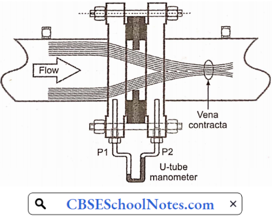
- As shown in the adjacent diagram, a gasket is used to seal the space between the orifice plate and the flange surface, to prevent leakage.
- Sections 1 and 2 of the Orifice meter are provided with an opening for attaching a differential pressure sensor (u-tube manometer, differential pressure indicator).
- Orifice meters are built in different forms depending upon the application-specific requirement, the shape, size, and location of holes on the orifice plate
Describe the orifice meter specifications as per the following:
- Concentric orifice plate.
- Eccentric orifice plate.
- Segment orifice plate.
- Quadrant edge orifice plate.
Orifice Meter Working:
The fluid flows inside the Inlet section of the Orifice meter having a pressure of P1. As the fluid proceeds further into the converging section, its pressure reduces gradually and it finally reaches a value of P2 at the end of the converging section and enters the cylindrical section.
- The differential pressure sensor connected between the inlet and the cylindrical throat section of the Orifice meter displays the pressure difference (P1-P2).
- This pressure difference is in direct proportion to the flow rate of the liquid flowing through the Orifice meter.
- Further, the fluid passes through the Diverging recovery cone section and the velocity reduces thereby regaining its pressure.
- Designing a lesser angle of the diverging recovery section helps more in regaining the kinetic energy of the liquid.
Orifice Meter Applications :
- Natural gas.
- Water treatment plants.
- Oil filtration plants.
- Petrochemicals and refineries.
Orifice Meter Advantages :
- The orifice meter is very cheap compared to other types of flow meters.
- Less space is required to install and hence ideal for space-constrained applications.
- The operational response can be designed with perfection.
- Installation direction possibilities: Vertical/Horizontal/Inclined.
Orifice Meter Disadvantages:
- Easily gets clogged due to impurities in gas or in unclear liquids.
- The minimum pressure that can be achieved for reading the flow is sometimes difficult to achieve due to limitations in the vena-contracta length for an orifice plate
- Unlike venturi meters, downstream pressure cannot be recovered in orifice meters.
- Overall head loss is around 40% to 90% of the differential pressure.
- Flow straighteners are required at the inlet and the outlet to attain streamlined flow thereby increasing the cost and space for installation.
- Orifice plates can get easily corroded with time thereby entailing an error.
- The discharge coefficient obtained is low.
Rotometer
- A rotometer is an example of a variable area meter.
- A variable area meter is a meter that measures fluid flow.
- Allowing the cross-sectional area of the device to vary in response to the flow causes some measurable effect that indicates the rate
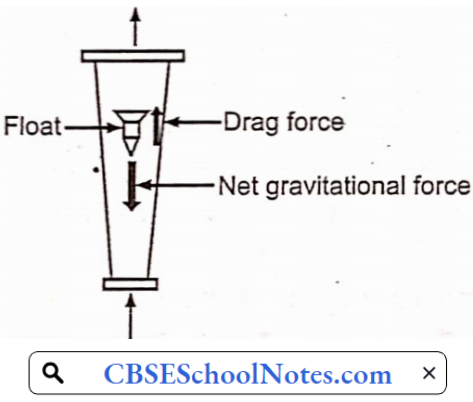
Rotometer Construction and Working:
The rotometer consists of a gradually tapered tube; it is arranged in a vertical position. The tube contains a float, which is used to indicate the flow of the fluid.
This float will be suspended in the fluid while fluid flows from the bottom of the tube to the top portion.
- The entire fluid will flow through the annular space between the tube and float.
- The float is the measuring element. The tube is marked with the divisions and the reading of the meter is obtained from the scale reading at the reading edge of the float.
- Here to convert the reading to the flow rate a calibration sheet is needed.
- For higher temperatures and pressure, where glass is not going to withstand, we use metallic tapered tubes.
- In metallic tubes, the float is not visible so we use a rod, which is called extension, which will be used as an indicator.
- Floats may be constructed using different types of materials from lead to aluminum glass or plastic.
- Stainless steel floats are common. According to the purpose of the meter, a float shape will be selected.
Rotometer Advantages :
- The pressure drop is constant.
- No special fuel or external energy is required to pump.
- Very easy to construct and we can use a wide variety of materials to construct.
Rotometer Disadvantages:
Due to its use of gravity, a rotometer must always be vertically oriented and right way up, with the fluid flowing upward.
- Due to its reliance on the ability of the fluid or gas to displace the float, graduations on a given rotometer will only be accurate for a given substance at a given temperature.
- The main property of importance is the density of the fluid; however, viscosity may also be significant.
- Floats are ideally designed to be insensitive to viscosity; however, this is seldom verifiable from manufacturers’ specifications.
- Either separate rotometers for different densities and viscosities may be used, or multiple scales on the same rotometer can be used.
- Rotometers normally require the use of glass (or other transparent material), otherwise the user cannot see the float.
- This limits their use in many industries to benign fluids, such as water.
- Rotometers are not easily adapted for reading by machine; although magnetic floats that drive a follower outside the tube are available.
Flow Of Fluids in Pharmaceutical Engineering Multiple Choice Questions
Question 1. A manometer is used to measure
- Pressure in pipes
- Atmospheric pressure
- Very low pressures
- Difference of pressure between two points
Answer: 3. Very low pressures
Question 2. A piezometer is used to measure
- Pressure in pipes
- Atmospheric pressure
- Very low pressure
- Difference of pressure between two points
Answer: 1. Pressure in pipes
Question 3. A differential manometer is used to measure
- Pressure in pipes
- Atmospheric pressure
- Very low pressure
- Difference of pressure between two points
Answer: 4. Difference of pressure between two points
Question 4. Which one of the following is known as fluid?
- Always expands until it fills in the container
- Cannot be subjected to shear, forces
- Cannot remain at rest under the action of any shear forces
- Practically compressible
Answer: 3. Cannot remain at rest under the action of any shear forces
Question 5. Which one of the following factors is responsible for the frictional factor, f, of a rough pipe and turbulent flow?
- Relative roughness
- Reynolds number
- Reynolds number and Relative roughness
- The size of the pipe and the discharge
Answer: 1. Relative roughness
Question 6. How many liquids are used in the differential manometer?
- 3
- 2
- 4
- 1
Answer: 2. 2
Question 7. Reynolds number is a ratio of the
- Elastic forces to pressure forces
- Gravity forces to inertial forces
- Inertial forces to viscous forces
- Viscous forces to inertial forces
Answer: 3. Inertial forces to viscous forces
Question 8. Which experiment is performed to study the flow of fluids?
- Bernoulli’s
- Orifice meter
- Reynolds
- Stokes
Answer: 1. Bernoulli’s
Question 9. The loss of head sudden enlargement in a pipe depends on one of the following differences
- Diameters
- Flow rates
- Surface area
- Viscosities
Answer: 3. Surface area
Question 10. Reynolds’ number depends on one of the following factors
- Roughness of the pipe
- Viscosity of the liquid
- Surface area of the pipe
- The volume of the liquid
Answer: 3. Surface area of the pipe