Materials Of Plant Construction
Several pieces of equipment are used in the pharmaceutical industry made up of different materials. The processing of the pharmaceutical industry involves the use of many types of chemicals that can destroy the construction material. Further. some processes involve high pressure, temperature etc. so the selection of materials for plant construction becomes very important to run the industry effectively.
Factors Influencing the Selection of Materials of Construction:
The selection of a material for the construction of equipment depends on the following properties:
- Chemical factors
- Contamination of the product
- Corrosion of material of construction
- Physical factors
- Strength
- Wear properties
- Thermal expansion
- Cleaning
- Mass
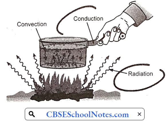
- Thermal conductivity
- Ease of fabrication
- Sterilization
- Transparency
- Economic factors
1. Chemical factors:
During the processing, every time a chemical substance or drug comes in direct contact with the equipment. Therefore, the product can get contaminated with the construction material or the construction material may get destroyed due to such direct contact (we can be called it corrosion).
- Contamination of product: Contamination of product due to construction material may result in a change in color of the product or there may be an occurrence of degradation of product due to chemical reaction. Leeching of glass may make aqueous products alkaline. This alkaline medium will be hazardous to the products which are unstable in alkaline medium. Heavy metals such as lead inactivate penicillin.
- Corrosion of material of construction: The products may be corrosive in nature. They may react with the material of construction and destroy it. The life of the equipment is reduced. Extreme pH, strong acids, strong alkalies, powerful oxidizing agents, tannins etc react with the materials, hence some alloys having special chemical resistance are used.
2. Physical factors:
- Strength: Many processes in pharmaceutical industries involve extreme pressure or stressed conditions.
- So the material must have sufficient physical strength to withstand the required pressure and stresses.
- Iron and steel can satisfy these properties. Tablet punching machine, die, upper and lower punch sets are made of stainless steel to withstand the very high pressure.
- Aerosol containers must withstand very high pressure, so tin plate container coated with some polymers are used.
- Plastic materials are weak so they are used in some packaging materials, like blister packs.
- Mass: For transportation lightweight packaging materials are used. Plastic, aluminum, and paper packaging materials are used for packing pharmaceutical products.
- Wear properties: When there is a possibility of friction between two surfaces, the softer surface wears off and these materials contaminate the products. For example, during milling and grinding the grinding surfaces may wear off and contaminate the powder. When a pharmaceutical product of very high purity is required ceramic and iron grinding surfaces are not used.
- Thermal conductivity: In evaporators, dryers, stills, and heat exchangers the materials employed have very good thermal conductivity. In this case, iron, copper, or graphite tubes are used for effective heat transfer.
- Thermal expansion: If the material has a very high thermal expansion coefficient then as temperature increases the shape of the equipment changes. This produces uneven stresses and may cause fractures. So such materials should be used that can maintain the shape and dimension of the equipment at the working temperature.
- Ease of fabrication: During the fabrication of equipment, the materials undergo various processes such as casting, welding, forging mechanization, etc.
- For example: Glass and plastic may be easily molded into containers of different shapes and sizes. Glass can be used as lining material for reaction vessels.
- Cleaning: Smooth and polished surfaces make cleaning easy. After an operation is complete, the equipment is cleaned thoroughly so the previous product cannot contaminate the next product. Glass and stainless steel surfaces can be smooth and polished and, hence are easy to clean.
- Sterilization: In the production of parenteral, ophthalmic, and bulk drug products all the equipment is required to be sterilized. This is generally done by introducing steam under high pressure. The material must withstand this high temperature (121°C) and pressure (15 pounds per square inch). If rubber materials are there it should be vulcanized to withstand the high temperature.
- Transparency: In reactors and fermentors, a visual port is provided to observe the progress of the process going on inside the chamber. In this case, borosilicate glass is often used.
In parenteral and ophthalmic containers the particles, if any, are observed from with polarized light. The walls of the containers must be transparent to see through it. Here also glass is the preferred material.
3. Economic factors:
The initial cost of the equipment depends on the material used. Several materials may be suitable for construction from physical and chemical points of view, but from all the materials only the cheapest material is chosen for the construction of the equipment.
Materials that require lower maintenance cost are used because in long run it is economical.
Materials used for Plant Construction Classification
- Metals:
- Ferrous metals – Cast.iron, stainless steel, steel carbon.
- Non-ferrous- Aluminium, lead.
- Non-metals:
- Inorganic- Glass.
- Organic- Rubber, plastics..
1. Ferrous metals:
1. Cast Iron:
This iron consists of carbon of more than 1.5%. A different proportion of carbon confers different properties to the steel.
Cast Iron Properties:
- Cast iron is resistant to concentrated sulfuric acid, nitric acid and dilute alkalis.
- Cast iron is attacked by dilute sulfuric acid, dilute nitric acid and dilute and concentrated hydrochloric acid.
- Cast iron has low thermal conductivity.
- It is not corrosion resistant hence it is alloyed with Silicon, Nickel or Chromium to produce corrosion resistance.
- It is brittle so it is tough to machine.
Cast Iron Applications:
- It is used as support for plants.
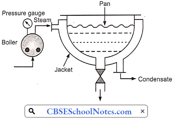
- Thermal conductivity is low hence used as the outer wall of the steam jacket.
- It is cheap and hence used in place of more expensive materials by coating with enamel or plastic.
2. Carbon Steel or Mild Steel:
Mild steel (or carbon steel) is an iron alloy that contains a small percentage of carbon (less than 1.5%).
Carbon Steel or Mild Steel Properties:
- It has greater mechanical strength than cast iron.
- It is easily weldable.
- Has limited corrosion resistance. This property can be increased by proper alloying.
- It reacts with caustic soda, and brine (concentrated NaCI solution).
Carbon Steel or Mild Steel Applications:
- Used for the construction of bars, pipes, and plates.
- Used to fabricate large storage tanks for water, sulfuric acid, organic solvents etc.
- Used as the supporting structure of grinders and bases of vessels.
3. Stainless Steel:
Stainless steel is an alloy of iron usually of nickel and chromium. For pharmaceutical use stainless steel contains 18% chromium and 8% nickel. This steel is called 18/8 stainless steel.
Stainless Steel Properties:
- It is heat resistant.
- Corrosion resistant.
- Ease of fabrication.
- Cleaning and sterilization is easy.
- Has good tensile strength.
- During heat welding the corrosion resistant properties of stainless steel may be reduced due to deposition of carbide precipitate at the crystal grain boundaries.
- This steel is stabilized by the addition of minor quantities of titanium, molybdenum or niobium.
Stainless Steel Applications:
- Storage and extraction vessels, evaporators, and fermenting vessels.
- Small apparatus like funnels, buckets, and measuring vessels.
- Sinks and bench tops.
- In penicillin production plants nearly all equipment is made of stainless steel.
2. Non-ferrous metals:
Aluminium:
Aluminum Properties:
- Pure aluminium is softer and more corrosion-resistant than its alloys. Small percentages of manganese, magnesium, or silicon produce strong, corrosion resistant aluminum alloys – Duralumin
- It is attacked by mineral acids, alkali, mercury and its salts.
- It is resistant to strong nitric acid.
- It is resistant to acetic acid due to the formation of a gelatinous surface film of aluminum subacetate.
- Low density hence lighter.
Aluminum Applications:
- The salts of aluminum are colorless and non-toxic to micro-organisms, hence used for fermenting vessels for the biosynthetic production of citric acid, gluconic acids and streptomycin.
- Used for making extraction and absorption vessels in preparation of antibiotics.
- Storage vessels of acetic acid and ammonia.
- Plants for nitric acid is used.
- Because of its lightness large containers such as drums, barrels, and road and rail tankers are made with aluminum.
3. Inorganic non-metals
Glass Preparation:
- Glass is composed principally of sand (Silica – SiO2), Soda-ash (Na2CO3 – Sodium carbonate), and limestone (CaCO3 – Calcium carbonate).
- Glass made from pure silica consists of a three-dimensional network of silicon atoms each of which is surrounded by four oxygen atoms and in this way, the tetrahedra are linked together to produce the network.
Glass prepared from pure silica requires a very high temperature to fuse, hence ash and lime is used to reduce the melting point.
1. Glass made of pure silica has a network: Properties:
- It is very hard.
- It is chemically resistant.
- The melting point is very high so it is very difficult to mould.
2. Glass made of pure silica + NaO2: Properties:
- The structure is less rigid so low melting point and is easier to mold.
- The glass is too rapidly attacked by water and NaOH is leached out of the glass.
3. Pure silica + CaO (or BaO, MgO, PbO and ZnO): Properties:
- Divalent oxides do not break the network of pure silica but only push the tetrahedron apart. It is more rigid than the soda-silica network.
- Since the bond is stronger, hence chemical reactivity is lowered.
4. Pure silica + Boric (B2O3) or Aluminium oxide (Al2O3):
- Since boric oxide is acidic, it does not disrupt the network of silica but forms tetrahedron itself; however, these tetrahedrons are not of the same size as silicon tetrahedra.
- Therefore, the lattice becomes distorted, and this produces flexibility.
- It is chemically resistant.
Glass Container Advantages:
- They are quite strong and rigid.
- They are transparent which allows the visual inspection of the contents; especially in ampoules and vials.
- They are available in various shapes and sizes. Visually elegant containers attract the patients.
- Borosilicate (Type-1) and Neutral glasses are resistant to heat so they can be readily sterilized by heat.
- Glass containers can be easily cleaned without any damage to its surface
- For example: Scratching or bruising.
- Borosilicate type of glass is chemically inert. Treated soda lime glass has a chemically inert surface.
- As the composition of glass may be varied by changing the ratio of various glass constituents the proper container according to desired qualities can be produced.
- They do not deteriorate with age if provided with proper closures.
- Photosensitive drugs may be saved from UV rays by using amber color glass.
- They are cheaper than other packaging materials.
Glass Container Disadvantages:
- They are brittle and break easily.
- They may crack when subject to sudden changes in temperatures.
- They are heavier in comparison to plastic containers.
- Transparent glasses give passage to UV light which may damage the photosensitive drugs inside the container.
- Flaking: From simple soda-lime glass the alkali is extracted from the surface of the container and a silicate-rich layer is formed which sometimes gets detached from the surface and can be seen in the contents in the form of shining plates – known as ‘flakes’ and in the form of needles – they are known as ‘spicules’. This is a serious problem, especially in parenteral preparations.
- Weathering: Sometimes moisture is condensed on the surface of a glass container which can extract some weakly bound alkali leaving behind a white deposit of alkali carbonate to remain over there, further condensation of moisture will lead to the formation of an alkaline solution which will dissolve some silica resulting in loss of brilliance from the surface of glass – called weathering.
To prevent weathering, the deposited white layer of alkali carbonates should be removed as early as possible by washing the containers with a dilute solution of acid and then washing them thoroughly with water.
5. Lead:
It is used to make collapsible tubes for topically applied products. It is very cheap. In pharmaceutical industries, its use is very limited due to its toxic nature.
Lead Disadvantage:
It has a low melting point and hence possesses poor structural qualities.
6. Copper:
- Copper is malleable and ductile. It has eight times more thermal conductivity than steel. It is attacked by nitric acid in all concentrations, by hot concentrated HCl and H2SO4.
- It is used in pharmaceutical industries after tin coating. It is used for heating pans, evaporators, and stills. It is more prone to corrosion.
- Other non-ferrous metals are silver, nickel, chromium, etc.
4. Inorganic nonmetal
1. Plastic:
Plastics can be categorized as:
- Rigid material
- Flexible material
- Coatings and linings
- Cement and filters
Keebush is an example of a rigid material. It is a phenolic resin with various inert fillers. It can be machined, welded, and worked and is resistant. It can be used for gears, bearings, and similar items with a noise reduction compared to iron. Its weight is about 2/4th that of iron.
It is resistant to corrosion except oxidizing substances and strong alkalis, pipes, fittings, valves, pumps, fans, ducts and made using this material.
- Polyethylene is the cheapest plastic. It is unaffected by most solvents, strong acids; and alkalies.
- Its density ranges from 0.91 to 0.96 determines its stiffness, moisture vapor, transmission, stress cracking, and translucency.
- The stiffness and stress resistance increase with density and permeability to gases decreases.
- Polypropylene has similar chemical resistance as polyethylene but it can be used at higher temperatures. Hot aromatic and halogenated solvents soften it.
- Unplasticized polyvinyl chloride is very clear, tough, and inert but tends to crack readily.
- Plasticizers are added to overcome this weakness. Stabilizers, antioxidants and lubricants may also be added.
2. Rubber:
These are widely used as lining materials. Several synthetic rubbers have been developed, while none has all the properties of natural rubber, they are superior in one or more ways.
- The isoprene and polybutadiene rubbers are duplicates of natural ones. Natural rubber is resistant to dilute mineral acids, alkalies, and salts, but oxidizing media, oils, benzene and ketones attack it Hard and soft rubbers are frequently used for handling acids especially dilute aqueous solutions.
- They cannot resist oxidizing agents and are swelled by organic solvents. Soft rubber is used as a lining for steel while hard rubber is used alone: Hard rubber is made by adding 25% or more of sulphur to natural or synthetic rubber and as such is hard and strong.
- Synthetic rubbers are becoming of increasing importance due to their superiority to natural rubber in many properties such as resistance to oxidation, solvents, oils, and many chemicals.
- Neoprene rubber is resistant to attack, by sunlight, oils, aromatic or halogenated solvents. Styrene rubber has chemical resistance similar to natural. Nitrile rubber is known fat resistance to oils and solvents.
Corrosion
Corrosion is a natural process, which converts a metal to a more chemically-stable form, such as its oxide, hydroxide, or sulfide.
It is the gradual destruction of materials (usually metals) by chemical and/or electrochemical reactions with their environment.
- Corrosion can be defined as the reaction of metallic material with its environment, which causes undesirable changes in the material and can result in a functional failure of the metal.
- Corrosion can also occur in materials other than metals, such as ceramics or polymers. Corrosion degrades the useful properties of materials and structures including strength, appearance, and permeability to liquids and gases.
- Corrosion can be concentrated locally to form a pit or crack, or it can extend across a wide area, corroding the surface. Because corrosion is a diffusion-controlled process, it occurs on exposed surfaces.
- As a result, methods to reduce the activity of the exposed surface, such as passivation and chromate conversion, can increase a material’s corrosion resistance.
Corrosion Theories
The metal surface undergoes an electrochemical reaction with the moisture and oxygen in the atmosphere. This- theory is called as electrochemical theory of corrosion. The mechanism involves the formation of galvanic cells (anodic and cathodic areas), by different metals or in different areas on the same piece of metal. When galvanic cells are formed on different metals, the corrosion is known as galvanic corrosion.
1. Corrosion reaction on single metal:
A single piece of metal (Fe) when comes in contact with acid (HCI ) small galvanic cells may be set up on the surface. Each galvanic cell consists of anode regions and cathode regions.
Reaction at anode:
Fe on the iron leaves two electrons in the metal and itself becomes Fe++ ion. Fe++ ion is soluble in water, so it is released in the medium. Thus the iron surface is corroded.
Reaction at the cathode:
The released electron is conducted through the metal piece into the cathode region. Two electrons are supplied to two protons (H+) to form two atoms of H. Hydrogen atoms are unstable, hence two H atoms will combine to form a molecule of stable H2. In the absence of acid, water itself dissociates to generate H+ Ions.
2H+ + 2e–→ H2
Hydrogen (H2) forms bubbles on the metal surface. If the rate of hydrogen formation is very slow then a film of H2 bubbles will be formed that will slow down the cathode reaction, hence the rate of corrosion will slow down.
If the rate of hydrogen production is very high then hydrogen molecules cannot form the film on the surface. So the corrosion proceeds rapidly.
2. Corrosion reactions between metals:
If two metals come in contact with a common aqueous medium then one metal will form an anode and the other will form a cathode. Now if both the metals are connected with a wire the reaction will proceed. Anode metal will be corroded and hydrogen will form at the cathode.
For example:
If a zinc and a copper plate is immersed in an acidic medium then zinc will form an anode and will be corroded while hydrogen will be formed at the copper plate.
Anode reaction: Zn→ Zn++ + 2e–
Cathode reaction: 2H+ + 2e–→ H2
So anode will be corroded and hydrogen will be evolved at the cathode.
3. Corrosion involving oxygen:
The oxygen dissolved in the electrolyte can react with accumulated hydrogen to form water. Depletion (reduction) of the hydrogen layer allows corrosion to proceed.
At cathode: O2 + 2H2→ 2H2O
The above reaction takes place in an acid medium. When the medium is alkaline or neutral oxygen is absorbed. The presence of moisture promotes corrosion.
Corrosion Types
1. General Attack Corrosion:
It is also known as uniform attack corrosion, general attack corrosion is the most common type of corrosion and is caused by a chemical or electrochemical reaction.
- That results in the deterioration of the entire exposed surface of a metal.
- Ultimately, the metal deteriorates to the point of failure.
- General attack corrosion accounts for the greatest amount of metal destruction by corrosion but is considered as a safe form of corrosion, because it is predictable, manageable, and often preventable.
2. Localized Corrosion:
Unlike general attack corrosion, localized corrosion specifically targets one area of the metal structure. Localized corrosion is classified as one of three types:
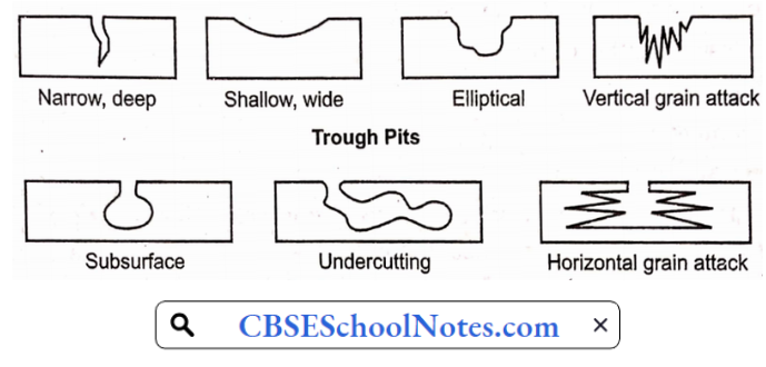
- Pitting: Pitting results when a small hole, or cavity forms in the metal, usually as a result of the de-passivation of a small area.
- This area becomes anodic, while part of the remaining metal becomes cathodic, producing a localized galvanic reaction.
- The deterioration of this small area penetrates the metal and can lead to failure.
- This form of corrosion is often difficult to detect because it is relatively small and may be covered and hidden by corrosion-produced compounds.
- Crevice corrosion: Similar to pitting, crevice corrosion occurs at a specific location. This type of corrosion is often associated with a stagnant micro-environment, like those found under gaskets and washerÿnd. clamps. Acidic conditions or a depletion of oxygen in a crevice can lead to crevice corrosion.
- Filiform corrosion: Occurring under painted or plated surfaces when water breaches the coating, filiform corrosion begins at small defects in the coating and spreads to cause structural weakness.
3. Galvanic Corrosion:
Galvanic corrosion, or dissimilar metal corrosion, occurs when two different metals are ‘ located together in a corrosive electrolyte. A galvanic couple forms between the two metals, where one metal becomes the anode and the other the cathode. The anode, or sacrificial metal corrodes and deteriorates faster than it would alone, while the cathode deteriorates more slowly than it would otherwise.
Three conditions must exist for galvanic corrosion to occur:
- Electrochemically dissimilar metals must be present.
- The metals must be in electrical contact.
- The metals must be exposed to an electrolyte.
- Subsurface Horizontal grain attack
4. Environmental Cracking:
Environmental cracking is a corrosion process that can result from a combination of. environmental conditions affecting the metal. Chemical, temperature and stress-related conditions can result in the following types of environmental corrosion:
- Stress Corrosion Cracking (SCC).
- Corrosion fatigue.
- Hydrogen-induced cracking.
5. Flow-Assisted Corrosion (FAC):
Flow-assisted corrosion, or flow-accelerated corrosion results when a protective layer of oxide on a metal surface is dissolved or removed by wind or water, exposing the underlying metal to further corroding and deterioration.
- Erosion-assisted corrosion.
- Impingement.
- Cavitation.
6. Intergranular corrosion:
Intergranular corrosion is a chemical or electrochemical attack on the grain boundaries of a metal. It often occurs due to impurities in the metal, which, tend to.be present in higher contents near grain boundaries. These boundaries can be more vulnerable to corrosion than the bulk of the metal.
7. De-Alloying:
De-alloying, or selective leaching is the selective corrosion of a specific element in an alloy. The most common type of de-alloying is the de-zincification of unstabilized brass. The result of corrosion in such cases is a deteriorated and porous copper.
8. Fretting corrosion:
Fretting corrosion occurs as a result of repeated wearing, weight, and/or vibration on an uneven, rough surface. Corrosion, resulting in pits and grooves, occurs on the surface. Fretting corrosion is often found in rotation and impact machinery, bolted assemblies, and bearings, as well as to surfaces exposed to vibration during transportation.
9. High-Temperature Corrosion:
- Fuels used in gas turbines, diesel engines and other machinery, which contain vanadium or sulfates can during combustion, form compounds with a low melting point.
- These compounds are very corrosive towards metal alloys normally resistant to high temperatures and corrosion including stainless steel.
- High-temperature corrosion can also be caused by high-temperature oxidization, sulfidation, and carbonization.
Corrosion Factors influencing
The rate and extent of corrosion depends on the following factors:
Nature of the metal:
- Position in galvanic series: When two metals or alloys are in electrical contact in the presence of an electrolyte, the more active metal (or higher up in the series) suffers corrosion. The rate and severity of corrosion depend upon the difference in their positions, and the greater the difference the faster is the corrosion of the anodic metal.
- Relative areas of the anodic and cathodic parts: When two dissimilar metals or alloys come in contact, the corrosion of the anodic part is directly proportional to the ratio of areas of the cathodic part and the anodic part.
- Purity of metal: Impurities in a metal generally form minute or tiny electrochemical cells and the anodic parts get corroded. For example, zinc metal containing impurity (such as Pb or Fe) undergoes corrosion of zinc, due to the formation of local electrochemical cells.
- The physical state of metal: The rate of corrosion is influenced by the physical state of the metal. The smaller the grain size of the metal or alloy, the greater its solubility and hence greater its corrosion. Nature of surface film: The ratio of the volume of the metal oxide to the metal is known as a “specific volume ratio.” The greater the specific volume ratio, the lesser the oxidation corrosion rate. According to the Pilling- bedworth rule the volume of oxide film is greater than the metal from which metal oxide is formed, then the film is protected.
- Solubility of corrosion products: In electrochemical corrosion, if the corrosion product is soluble in the corroding medium, then corrosion proceeds at a faster rate. On the contrary, if the corrosion product is insoluble in the medium or thereby suppresses further corrosion.
- Volatility of corrosion products: If the corrosion product is volatile, it volatilizes as soon as it is formed, thereby leaving the underlying metal surface exposed for environmental attack. This causes rapid and- continuous corrosion.
Corrosion Control Methods
Corrosion is a destructive and silent process operating all ‘the time, at all levels, and in all establishments. Since corrosion is impracticable to eliminate, effective Corrosion Science and Engineering lies in controlling rather than preventing it. Corrosion of metals occurs when they come in contact with a corrosive environment. Therefore, metallic corrosion can be prevented by either changing the metal (or) altering the environment separating the metal from the environment (or) by changing the electrode potential of the metal.
1. Design Improvement:
A large number of corrosion failures are due to improper design of equipment and corrosion control can be therefore warranted at the design stage itself. The usual procedure followed at the design stage is to:
- Establish basic requirements.
- Selecting the most suitable protective method and carrying out the final design work.
Some of the most general points for design are given below:
- Structures should have simplified forms. A complicated shape having more angles, edges, and internal surfaces will be easily corroded.
- Avoid crevices to avoid trapping of moisture and dirt which results in increased corrosion.
- Avoid residual moisture by having proper drainage holes and ventilation. Avoid contact with absorbent material.
- Avoid galvanic corrosion by using suitable electrical insulators. Cheap and easily exchangeable corroding pieces (or) paints where the contact of two different metals is unavoidable.
2. Change of Metal:
- Mostly corrosion protection involves bulk alloying (or) surface coatings. Surface coatings may pose problems related to adhesion, thermal expansion compatibility, etc.
- Surface processing of metals has been improved by iron implantation technique and laser treatment which results in a homogeneous and single-phase surface layer.
- Recently, electron beam surface area glazing has been found to increase the clear life of iron base tool materials.
3. Change of Electrode Potential of the Metal:
Corrosion can be prevented by changing the electrode potential by taking the metal to the immune region or passive region; According to the Pourbaix diagram, this can be accomplished by making the potential of the cathode equal to the open circuit potential of the anode.
1. Cathodic Protection:
Cathodic protection is defined as the reduction or prevention of corrosion by making it a cathode in the electrolytic cell.
- There are two methods of applying cathodic protection to metallic structures, such as galvanic or sacrificial anode and impressed current method.
- In each method, a direct current supply is more available for the protection of metal structures.
- The choice of the method to be used depends, upon several economic and technical considerations.
Galvanic or sacrificial anode:
- It is possible to protect ship hulls from corrosion. An active metal, generally zinc is used as a sacrificial anode in contact with the corroding material.
- The two metals in contact form a galvanic cell, the terminals of which have been short-circuited.
Impressed current method:
In of cathodic protection, an external source of direct current is connected to the structure to be protected (works as the cathode), and an auxiliary electrode functions as the anode (also called a consumable electrode).
- Some important impressed current anodes are graphite, scrap iron, platinum, and lead-silver alloys. Power sources used in these systems are rectifiers, batteries, etc.
- The sacrificial anode system and impressed current anode system are complementary to each other.
- Cathodic protection can be applied to buried pipelines, underground cables, equipment for handling and storage of chemicals, steel structures in the marine atmosphere, hulls of ships, and oil-cargo-ballast tanks.
Some of the limitations of cathodic protection are:
- If polarization is too weak, materials remain exposed to a corrosive environment and remain unprotected.
- Results in stray-current corrosion in a neighboring unprotected buried structure. An application of cathodic current may lead to the destruction of passivity in certain passive alloys, such as stainless steel.
- If polarization is too high, certain metals such as lead and tin are attached by gasification, with the formation of gaseous hydrides, which can lead to the weakening and consequently disintegration of articles.
2. Anodic Protection:
Anodic protection is defined as the protection of a metal by maintaining it in a passive condition. This technique is based on the phenomenon of passivity. The metal to be protected is given a fixed potential to produce a passive film (of corrosion) on it and the structure is protected from a corrosive environment.
This method applies to metals which can obey the following conditions:
- The metal (or) alloy should have an active passive transition – For example: Fe, Ni, Cr, Ti, etc.
- It must require only a small current to maintain passivity.
- The passive range for it must be wide.
- Sufficient electrical conductivity of the aggressive medium to which metal (or) alloy is exposed.
- The cathode is connected to the negative poles of the power source and completes the electrical circuit. Some of the cathodes used are platinum, clad brass, chromium, nickel, steel, etc.
- To measure the potential of the structures to be protected, a reference electrode is needed.
- The reference electrodes used are calomel, Ag/AgCI, Hg/HgSO4, and Pt/PtO. These should be insoluble in corrosive fluid and have the potential that be stable concerning time.
- A potentiostat is necessary to maintain the potential at the required level.
Anodic Protection Advantages:
- In storage of ads.
- In fertilizer industries and some other chemical industries.
Anodic Protection Limitations:
- This method applies only to a few metals that can be passive under certain environments.
- This requires costly instruments like potentiostat.
This method cannot be used for metals exposed to an environment containing aggressive anions such as chloride.
4. Using of coating:
Corrosion can be prevented by separating the metal from the corrosive environment by using protective coatings. Metallic and non-metallic coating are the. two types. The characteristics of these are:
- Good corrosion resistance.
- Perfect adherence to the underlying metal.
- Continuity to cover the metal surface completely.
Cathodic and anodic metallic coating provides a physical barrier between the environment and discontinuity in the coating will result in a localized attack,
For example Brass, chromium (or) gold coating on steel as a cathodic coating. Zinc and aluminum coating on steel as an anodic coating.
Material Handling Systems
Material handling systems in the pharma industry mainly involve the transportation of materials. The materials can be in any physical form like solid, liquid, or gas. So different types of handling instruments are required for different types of materials. Material handling is the movement, protection, storage, and control of materials and products throughout manufacturing, warehousing, distribution, consumption and disposal.
Material Handling Systems Integration:
Placing together several different materials handling technologies to create a complete functional system is important for any warehouse. Solutions contain as many or as few components as are required to accomplish the goals of your project, and the right combination can yield many benefits
Handling Of Solids
Handling Of Solids Conveyors: Clean-in-Place Conveying Systems:
Conveyors for medical and pharmaceutical warehouses are generally designed with specific requirements in mind, including ease of cleaning, disassembly, and maintenance.
- They must also be designed to meet containment level regulations.
- The types of conveyors available include those maximized for containment, systems integration for batch and continuous processing, and clean-in-place (CIP) designs.
- The clean-in-place option is popular because it allows virtually every component of the system to be easily cleaned without taking the conveyor apart.
- With CIP systems, cleaning is faster, requires less labor, is repeatable, and presents less risk of chemical exposure to workers.
- CIP systems are fully automated including features such as programmable logic, multiple balance tanks, valves, data acquisition, and custom spray nozzle systems.
When sanitary requirements are a factor, stainless steel conveyors are an option. These designs are also easy to clean and are designed to prevent cross-contamination.
Types of Conveyors:
Conveyors come in many shapes and sizes to meet just about any warehouse need. Here’s a look at some commonly used conveyors:
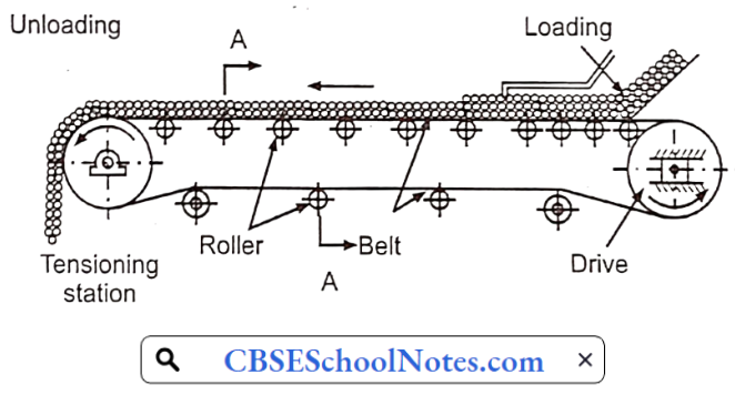
- Pharmaceutical Belt Conveyor: The belt conveyor is a simple solution that uses pulleys to quickly transport products along a belt. It is a popular choice because it’s easy to use and flexible. When configured specifically to your warehouse, belt conveyors are very economical because their speed and efficiency reduce labor costs without compromising accuracy
- Flexible/Extendable Conveyor: This is popular when versatile speed performance is needed. It can be installed in minutes and is ideal for fast loading and unloading of trucks and cost-effectiveness.
- Line-shaft Conveyor: This conveyor is a cost-effective solution to order transportation and accumulation requirements. It employs a line shaft with drive spools that line the shaft along the length of the conveyor. The spools have tensioned urethane bands that attach to gravity rollers; as the line shaft spins, it turns the spools, which then spin the urethane bands on the rollers, which causes them to turn. The spools are engineered to slip, which allows maximum accumulation without product damage.
- Heavy-duty Roller Conveyor System: This system delivers automation to the order fulfillment operation. Automation provides the benefits of systems-driven decision-making versus human-driven decision-making, resulting in better pick efficiencies, improved quality control, and lower process times.
- Vertical Conveyor: This is an excellent solution if you want to elevate a product within a small footprint. This type of conveyor can easily transport products between multiple levels speedily and safely. The conveyor system can be designed to meet specific space constraints using C- and S-shaped configurations. A vertical conveyor can accommodate up to 50 units per minute and can transport totes, cartons, trays, and pallets. It is designed for low maintenance, vibration-free, and quiet operation
- Spiral Conveyor: A spiral conveyor is great for transporting products between multiple elevations. It can handle a single infeed and single discharge and up to two or more discharges. It can be employed for lifting or lowering products. A continuous running belt results in high throughput with speeds of up to 200 FPM.
- Sortation Conveyor: This is an important part of an automated system. Sortation conveyor systems facilitate high product throughput, which is transported don dedicated lanes. The sortation logic is built upon specific business rules.
Handling Of Liquids In Pharmaceutical Industry
Pipes
- A pipe is a tubular section or hollow cylinder, usually but not necessarily of circular cross-section, used mainly to convey liquids and gases, slurries, powders, and masses of small solids. Pipes can be made up of metal alloys, ceramics, glass, plastics, etc.
- Pipes and tubings are specified in terms of their diameter and wall thickness. The diameter of steel pipes is the standard size.
- O.D. of all the pipes made with other materials also are matched with steel pipes. Therefore, these standard pipe sizes are called as IPS (Iron pipe size) or NPS (normal pipe size).
- The wall thickness of pipes is indicated by its schedule number which increases with the thickness. Ten schedule numbers 10, 20, 30, 40, 60, 80, 100, 120, 140, 160 are used.
Fittings
The fittings are used to join the two pipes. There are different types of fittings
- Screwed fittings: In this type ends of the pipe are threaded externally with the threading tool. The thread is tapered and the few threads farthest from the end of the pipe are imperfect so that a tight joint is formed when the pipe is screwed into the fitting.
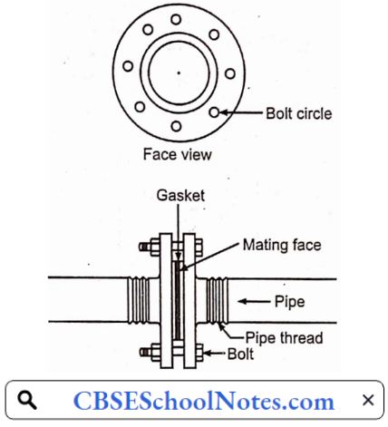
- Flanged joints: The flanged joint design means that pipes are secured by external screws, providing additional joint support for the transportation of substances at high pressure.
- Welded joints: For joining large diameter pipes for high-pressure service welding is the standard method. Welding makes stronger joints than screwing and does not weaken pipe walls as occurs in screwed fitting. These joints are leakproof.
Valves
Valves are the components that are used to stop or regulate the flow of fluid in its path.
Different types of valves are available depending on their applications listed below:
- Gate valve, Plug valve, and Ball valve- used for isolation only. Globe valve- used for throttling.
- Check valve- used for preventing reverse flow (non-return).
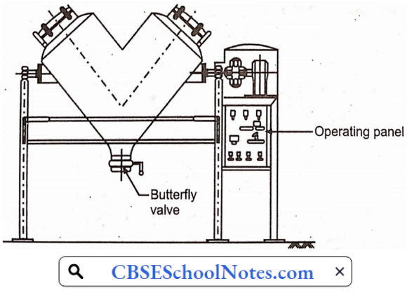
- Butterfly valve- used for isolation as well as throttling.
- Diaphragm valve- used for isolation as well as throttling.
Pumping and compression
A pump is a mechanical device used to increase the energy of the liquid. In most of cases pump is used for raising fluid from a lower level to a higher level. Several pumps have been developed to meet a variety of operating conditions.
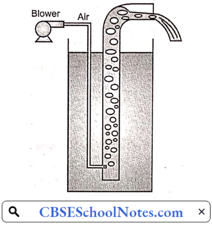
Airlift pump:
- An airlift pump is a pump that has low suction and moderate discharge of liquid and entrained solids.
- The pump injects compressed air at the bottom of the discharge pipe which is immersed in the liquid.
- The compressed air mixes with the liquid causing the air-water mixture to be less dense than the rest of the liquid around it and therefore is displaced upwards through the discharge pipe by the surrounding liquid of higher density.
- Solids may be entrained in the flow and if small enough to fit through the pipe, will be discharged with the rest of the flow at a shallower depth or above the surface.
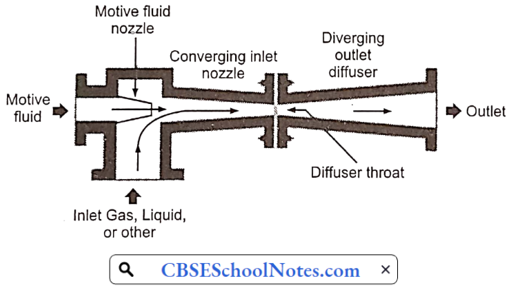
Jet pumps:
- Jet pumps are centrifugal pumps with an ejector (venturi nozzle) attached at the discharge outlet.
- They function based on the venturi effect of Bernoulli’s principle utilizing constriction to reduce pressure and provide suction.
- After the pump is primed, a motive fluid is pumped through a standard centrifugal pump and enters an ejector.
- At the throat of the converging section of the ejector, the pressurized fluid is ejected at high velocity.
- This creates a low pressure (vacuum) at the throat, drawing the target fluid (from a well or other source) up into the nozzle.
Reciprocating pumps:
- A reciprocating pump essentially consists of a piston or plunger which moves to and fro inside a cylinder.
- The cylinder is connected to the suction and delivery tube each of which provides a nonreturn valve called the suction valve and delivery valve.
- During the backward motion of the piston, a partial vacuum is created inside the cylinder.
- Because of this low-pressure water will rise from the well through the suction tube and fill the cylinder by forcing it to open the suction valve.
- This operation is known as suction stroke. In
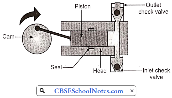
This stroke delivery valve will be closed and the suction valve will be open during this stroke. When the piston moves forward pressure is exerted on the liquid and due to this the suction valve closes and the delivery valve opens. The liquid is then forced up through the delivery pipe. This stroke is known as delivery stroke.
Materials Of Pharmaceutical Plant Construction Corrosion And Its Prevention Multiple Choice Questions
Question 1. A water attack test is performed on glass to find out the limits of
- Acid liberated
- Alkali liberated
- Conductivity
- Metal ions
Answer: 2. Alkali liberated
Question 2. Which one of the following is used m the construction of the outer jacket of the evaporating pan due to its low thermal conductivity?
- Aluminium
- Cast iron
- Copper
- Carbon steel
Answer: 2. Cast iron
Question 3. Which metal makes steel corrosion-free?
- Chromium and Nickel
- Copper and Selenium
- Tantalum and Molybdenum
- Titanium and Niobium
Answer: 1. Chromium and Nickel
Question 4. A severe form of corrosion that develops in highly localized areas of the metal surfaces is called________
- Erosion
- Galvanic corrosion
- Pitting corrosion
- Stress Corrosion
Answer: 3. Pitting corrosion
Question 5. Which one of the following is not a measure to control corrosion?
- Increasing the temperature of storage
- Pumping inert gas into solution
- Removing air from boiler feed water
- Shortening the time of exposure
Answer: 1. Increasing the temperature of storage
Question 6. In cathodic protection one of the following effects is suppressed
- Dissolution of anode
- Dissolution of cathode
- Dissolution of cathodic film
- Electric current
Answer: 2. Dissolution of cathode
Question 7. Which one of the following pumps are used when the liquid contains solids?
- Reciprocating pump
- Plunger pump
- Airjetpump
- Peristaltic pump
Answer: 2. Plunger pump
Question 8. In n plunger pump, the moving element follows which one of the mechanisms?
- One Direction
- Propelling
- Reciprocating
- Rotating
Answer: 3. Reciprocating
Question 9. Pumps are not used to increase one of the energy of liquids
- Kinetic energy
- Potential energy
- Pressure energy
- Radiant energy
Answer: 4. Radiant energy
Question 10. The belt conveyor moves mainly with the help of
- Drive pulley
- Idlers
- Non-troughing idlers
- Snubber idler
Answer: 1. Drive pulley


 ……………………………………… (5)